
Whether you are building a 3D printer, industrial equipment, or a robot, as long as a stepper motor is used, one question is unavoidable—how do you choose the driver IC? Choose correctly, and the motor runs quietly and smoothly; choose wrong, and it gets hot, loses steps, and is noisy, with debugging that makes you doubt life. This article explains the core parameters for driver IC selection + a quick selection method + a pitfall-avoidance guide all at once.
I. Rated Drive Current (RMS)
Stepper motors generate torque through current; the larger the current, the stronger the torque. So the first step in selecting a driver IC is to focus on its RMS (root mean square) current. This value represents the equivalent current the driver IC can continuously output and determines whether the IC can actually drive your motor—like a car's engine displacement: too small and it cannot move, too large and it wastes cost and power.
How to choose?
You can determine the required RMS value of the driver IC by checking the rated current on the motor nameplate; generally, it should be more than 10% higher to leave sufficient margin and avoid overheating during long-term full-load operation.
For example
| Motor model | Rated current (motor) | Driver IC |
| NEMA 17 standard motor | 1.2~1.7A | TMC2209(2A) |
| NEMA 23 standard motor | 2~3A | TMC5160(1~10A) |
Notes:
Some manufacturers' datasheets sometimes specify peak current. Peak current ÷ 1.41 ≈ RMS. For example, the DRV8825 is rated at 2.5 A peak, but the practically usable RMS is about 1.77 A. Comparing peak current directly with the motor nameplate can easily lead to undersizing. Peak current represents the maximum current the IC can momentarily handle; it determines whether the motor can deliver enough impact force at startup and sudden acceleration, and it also needs to be sufficient—be careful not to confuse the two.
2. Supply Voltage Range (VM)
The supply voltage range (VM) refers to the motor power supply voltage range over which the driver IC can operate normally. It is a physical compatibility threshold that determines whether the chip can be used in your system. Exceeding this range may damage the chip; if the voltage is too low, the drive capability will be insufficient and motor torque will decrease.
Key Selection Points
First confirm the system supply voltage, then choose a model whose VM range covers it with some margin.
For example, the TMC2209 has a VM range of 4.75 V to 29 V, so it matches 12 V desktop equipment systems very well and can also be used in 24 V systems, but the TMC2240 (4.5–36 V) is more recommended; for a 48 V industrial system, neither is suitable.
Special note: VM ≠ VCC
- VM: the motor supply rail, which supplies power to the motor windings; it has higher voltage and larger current and determines the motor's maximum speed and output power;
- VCC: logic supply, which supplies power to the chip's internal digital circuits, usually 3.3 V or 5 V; it has lower voltage and smaller current.
The former drives the motor coils to do work, while the latter supplies signals to the chip's "brain"; connecting them incorrectly will burn the chip.
3. Microstepping
The basic step angle of a stepper motor is usually 1.8° (full step). Microstepping means 'chopping' this full step into smaller steps so that the motor winding current is closer to a sine wave.
- With 16 microsteps → each step becomes 0.1125°;
- With 256 microsteps → each step is 0.007°.
Remember — the higher the microstep resolution, the smoother the motion and the quieter the sound, but the higher the pulse frequency requirement on the controller.
So first confirm the MCU's maximum pulse output frequency, then choose the microstep setting. If the MCU's clock frequency is insufficient, forcing a high microstep setting can actually cause step loss. For noise-sensitive applications (household, medical), high microstepping plus a silent mode is recommended; for high-speed applications (conveyor belts), use medium-to-low microstepping to ensure speed.
Note also: microstepping addresses motion smoothness, not mechanical positioning accuracy. Accuracy depends on the motor's manufacturing tolerances; 256 microstepping will not turn an engraving machine into a lithography machine.
4. Control Interface Types
The control interface is the “communication protocol” between the MCU and the driver IC. It determines how the MCU "commands" the IC, how much information can be read back (motor load, chip temperature, fault flags, etc.), and it also directly affects development effort.
There are three mainstream types—STEP/DIR (step/direction), UART, and SPI.
| Interface Type | Required Pins | Can Read Status | Development Difficulty | Suitable For |
| STEP/DIR (Step/Direction) | 2 wires (pulse + direction) | ❌ Cannot | ★☆☆ Easy | Beginners, quick validation |
| UART | 1 wire (single-wire serial) | ✅ Yes | ★★☆ Medium | Engineers with microcontroller basics |
| SPI | 4 wires (MOSI/MISO/CLK/CS) | ✅ Real-time, full-featured | ★★★ Complex | Experienced engineers |
Evaluate mainly two dimensions: ① whether motor status needs to be read; ② the development resources of the team/project. STEP/DIR is the simplest and can be used with any MCU, but it cannot sense the motor's operating status; UART is suitable for scenarios where the team has some development capability and wants to read status, and open-source firmware such as Marlin/Klipper has native support for it; SPI is the most complete in functionality, but requires handling timing and drivers yourself, making it suitable for mass-production projects or engineering scenarios requiring fine control.
5. Protection Features
When a driver IC is operating, it often encounters various abnormalities: motor stall causing overcurrent, prolonged full-load operation causing overheating, power supply fluctuations causing voltage drops, wiring errors causing short circuits, etc. The protection configuration determines whether, when an abnormality occurs, the IC withstands it itself, shuts down to protect itself, or simply burns out—this directly affects system reliability and repair costs.
Three standard features: overtemperature protection (OTP) prevents thermal damage; overcurrent protection (OCP) prevents stall from burning the coils and chip; undervoltage lockout (UVLO) prevents malfunction due to voltage drops. Short-circuit protection and stall detection are bonus features.
VI. Functional Integration Level
Which peripheral functions or advanced functional modules are integrated into the driver IC directly affects the system's PCB area, BOM count, and material cost. Generally, the more functions integrated into the driver IC, the simpler the external circuitry, but the higher the chip unit price.
- Integrated MOSFET: saves area and components and simplifies design, but current capability is limited; external MOSFET: power is flexible and adjustable and can drive higher current, but routing is more complex and additional components are required.
- Current sensing: some ICs integrate sampling, eliminating two high-power current-sense resistors; with external sensing, you need to add them on the board yourself, but you can flexibly choose the resistance value.
- Charge pump integration: the charge pump provides the gate drive voltage for the high-side MOSFET; when integrated, it eliminates the need for an external bootstrap capacitor solution.
Most driver ICs on the market today come with additional features, such as quiet operation algorithms and sensorless stall detection, and you can select them as needed. For low-power, space-constrained applications (consumer electronics, desktop devices), prioritize highly integrated ICs to reduce external components and layout difficulty; for high-power industrial solutions or those requiring flexible adjustment of drive capability, consider driver ICs with external MOSFETs to leave more room for power expansion.
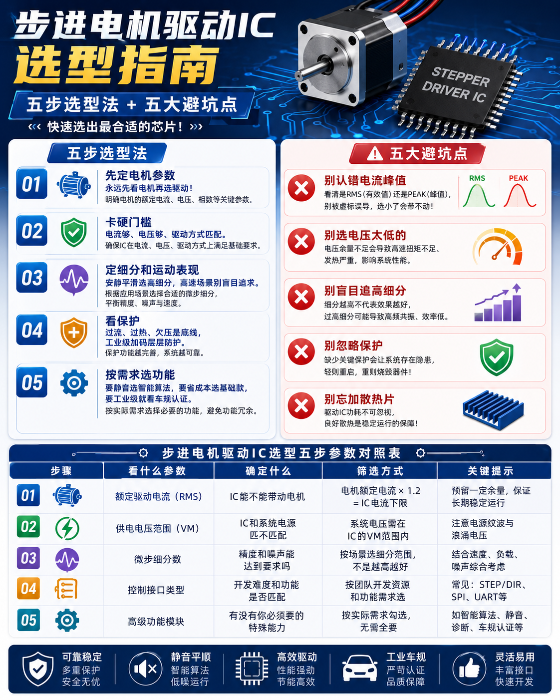
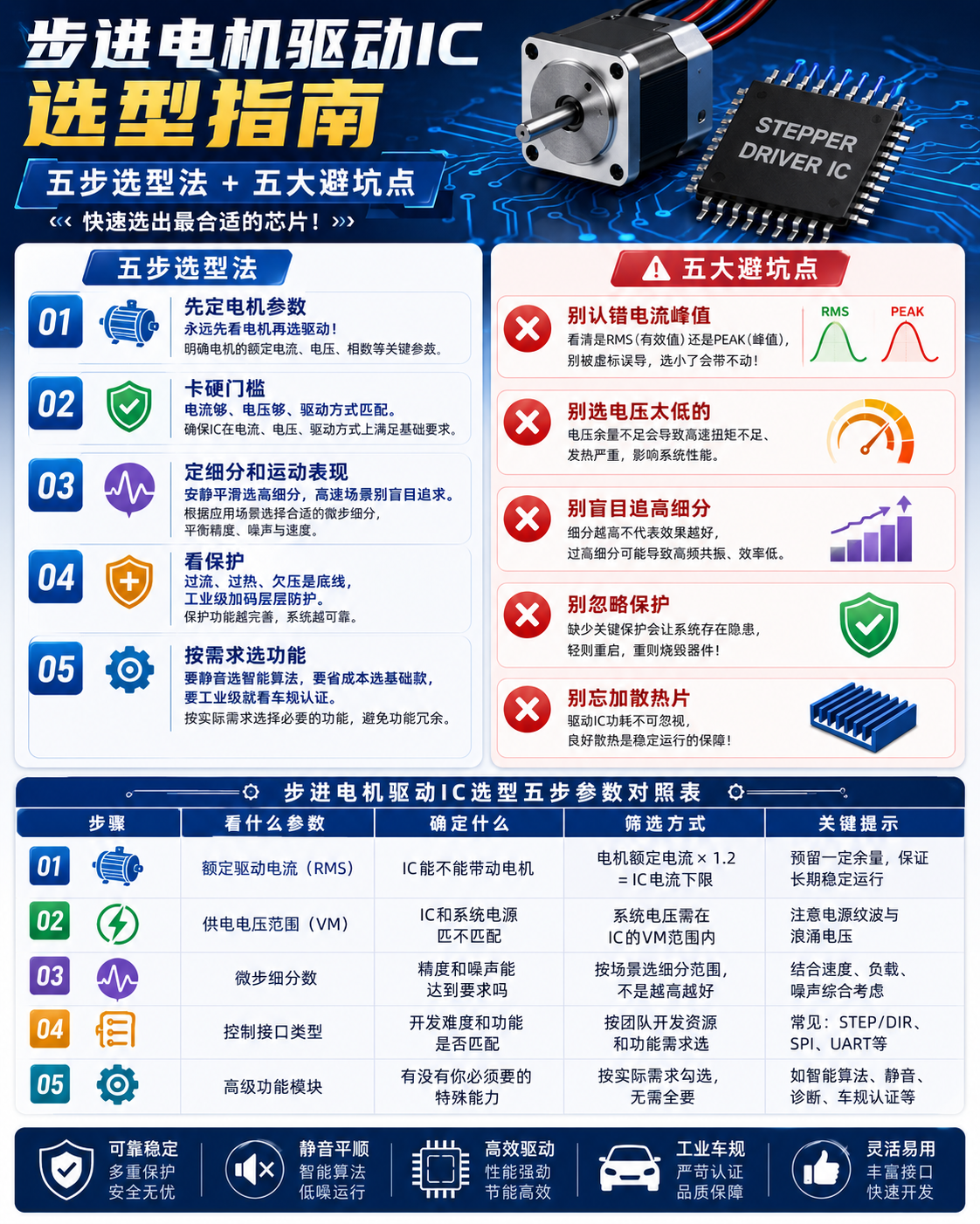
VII. Five-Step Selection Method
Finally, here is a summary of a five-step selection method, plus five pitfalls to avoid, to help you quickly select the right chip:
First and most important—define the motor parameters first. Always look at the motor before selecting the driver!
Step 2: Check the hard requirements—sufficient current, sufficient voltage, and a matching drive method.
Step 3: Determine microstepping and motion performance—choose high microstepping for quiet, smooth operation; in high-speed scenarios, do not pursue it blindly.
Step 4: Check protection—overcurrent, overtemperature, and undervoltage are the baseline; industrial-grade devices add layered protection.
Step 5: Choose functions based on requirements—for quiet operation, choose intelligent algorithms; to save cost, choose the basic version; for industrial-grade use, look for automotive-grade certification.
Five pitfalls to avoid: do not mistake the peak current; do not choose a device with too low a voltage; do not blindly chase high microstepping; do not ignore protection; do not forget to add a heat sink.
VIII. Conclusion
Selecting a stepper driver IC is essentially a parameter-matching game: use your motor parameters as the ruler to check the IC's hard specifications such as current, voltage, and interface, then choose the appropriate microstepping, interface, and advanced features based on the application scenario.
Of course, much of the above is based on practical experience and is provided for reference only. In actual projects, adjustments must be made according to the specific operating conditions (such as ambient temperature, vibration, electromagnetic interference, etc.). For critical projects, reliability comes first—remember to consult the original manufacturer's FAE or a senior hardware engineer.
For more information about stepper motor driver ICs, please contact: sales@chiplinkstech.com; 13924675549, Engineer Chen.
WeChat Official Account
