
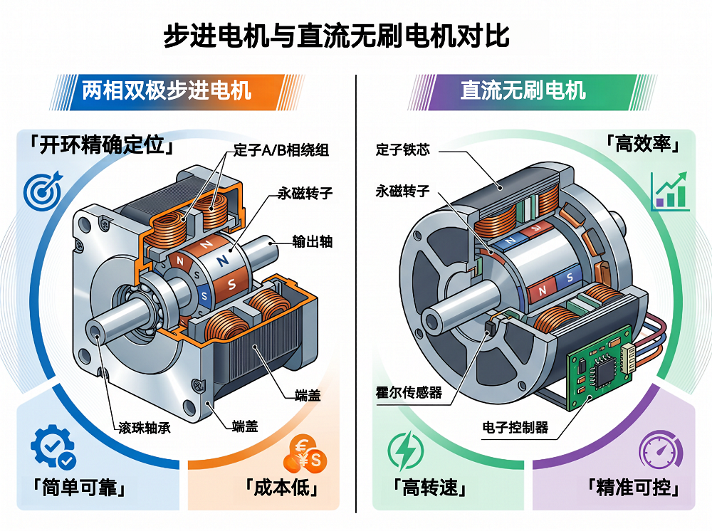
In the field of motion control, stepper motors and brushless DC (BLDC) motors are two types of motors that are often mentioned together.
In terms of market size, the global stepper motor market exceeded US$2 billion in 2024, with China accounting for more than 60%. In 3D printing, medical devices, security surveillance, and semiconductor equipment—wherever precise positioning is required—stepper motors are almost always turning. BLDC is larger, at about US$21 billion in 2024, with a compound annual growth rate above 8%. The rapid growth of new energy vehicles, industrial robots, and smart home appliances continues to expand the boundaries of BLDC applications. Both can precisely control position, but their internal logic and applicable scenarios differ greatly.
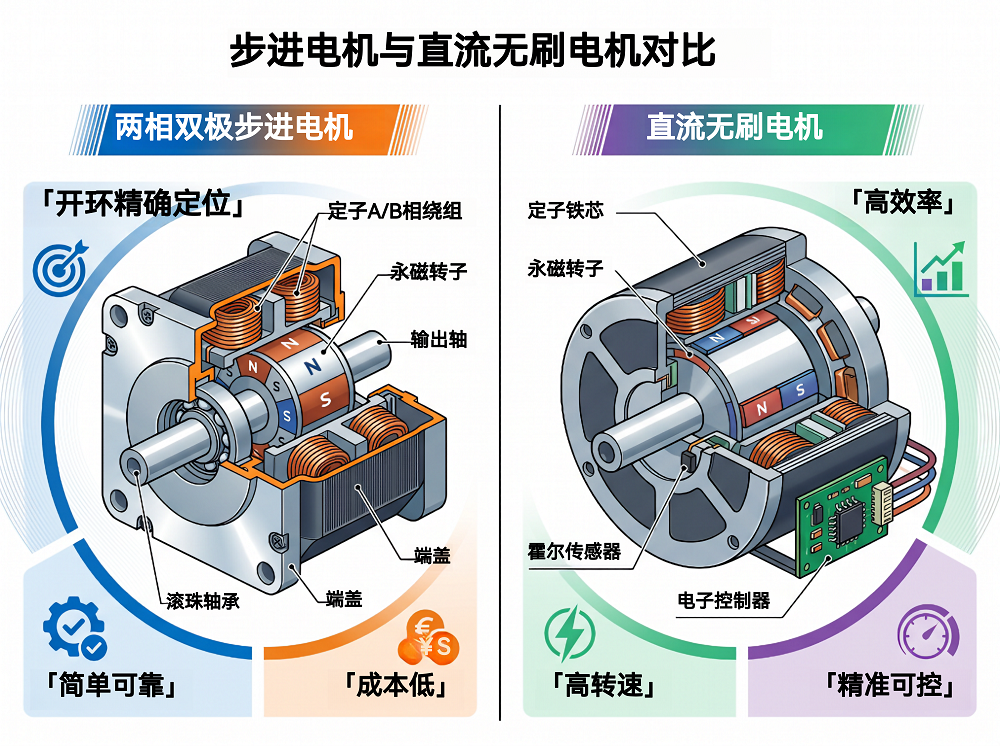
1. Stepper Motors
The so-calledstepper motor is an actuator that rotates a fixed angle each time it receives an electrical pulse signal. Its core feature is open-loop control: no encoder feedback is required; the number of pulses strictly corresponds to angular displacement—one pulse moves one step, and the number of pulses determines how far it moves.
It mainly consists of four parts:
- Stator, wound with multi-phase excitation coils; when energized, it generates a rotating magnetic field, which is the source of the driving force.
- Rotor, rotates under the action of the magnetic field; different rotor types determine the motor's performance characteristics.
- End caps and bearings, fix the relative position between the stator and rotor, ensuring coaxiality and mechanical stability.
- Output shaft, transmits the torque generated by the rotor to the load.
By rotor construction, stepper motors can be divided into three types:
- VR type, variable reluctance.The rotor is a soft-iron gear and has no permanent magnet. The step angle is relatively large, typically 15°, and there is no holding torque when power is removed. Accuracy is relatively low, and it is generally used in open-loop positioning applications that do not require high accuracy.
- PM type, permanent magnet.The rotor is a cylindrical permanent magnet, and the step angle ranges from 7.5° to 90°. It provides holding force when power is removed and offers medium accuracy; it is most commonly used in instrument drives and low-power positioning.
- HB type, hybrid.The rotor consists of two toothed iron cores sandwiching an axially magnetized permanent magnet, with the two tooth sections offset by half a tooth pitch. It combines the precise tooth pitch of VR motors with the permanent-magnet torque of PM motors, achieving a step angle as small as 0.9° and providing holding torque when power is removed. Most industrial stepper motors currently use this design.
The core of stepper motor drive principles is the calculation of the step angle and the selection of the excitation method.
Step angle refers to the mechanical angle through which the rotor rotates each time it receives a pulse. The general formula is: step angle = 360° / (number of rotor teeth × number of drive steps per electrical cycle).Here, the number of drive steps refers to the number of pulses required for the stator windings to complete one full energization cycle. Taking the most common two-phase HB-type 50-tooth motor as an example: with full-step four-step drive, the number of drive steps = 4, and the step angle = 360°/(50×4) = 1.8°; with half-step eight-step drive, the number of drive steps = 8, and the step angle = 0.9°.
Specifically forexcitation modes, there are four levels. The most basic is full-step, in which both phases are energized simultaneously; torque is stable, and it is the most commonly used.A step more advanced is half-step, in which single-phase and dual-phase energization alternate; the step angle is directly halved and operation is smoother. Beyond that is microstepping drive, which precisely controls the current in each phase with sine and cosine, can reduce the step angle to 1/256 of a full step, approximately 0.007 degrees, and makes operation so smooth that the eye cannot tell it is stepping.
| Excitation Mode | Step Angle | Torque | Features |
| Single-phase excitation | Full step | Small | Low power consumption |
| Two-phase excitation | Full step | Approx. single-phase × √2 | Most common |
| 1-2 phase excitation (half-step) | Half-step | Medium | Improved smoothness, doubled resolution |
| Microstepping drive | Full-step / 4–256 | High | Smoothest operation, with a minimum step angle as small as 0.007° |
As mentioned earlier, the core feature of stepper motors is open-loop precise positioning; therefore,the advantagesare also very direct: position error does not accumulate and remains within ±3% to ±5% of the step angle; torque is high at low speeds, so many applications do not require a reduction mechanism; the structure is simple, with no brushes and no commutator, giving high reliability; HB-type and PM-type motors provide holding torque when power is removed; start/stop is fast, forward/reverse operation is flexible, and the overall system cost is low.
However, open-loop control also brings several unavoidablelimitations. In the 100–300 rpm range, resonance is likely and can directly cause lost steps in severe cases; above 600 rpm, torque drops off sharply, efficiency is only 20% to 40%, and most of the power is dissipated as heat; noise is relatively high, and crawling may occur at low speed. Most critically, in open-loop mode the system has no way of knowing when steps are lost, and position deviation cannot be corrected.
To address the limitations of stepper motors, domestic and international driver chip manufacturers have mature solutions; below are some recommended driver selections:
On the international product side, Germany's Trinamic has been working on stepper drives for many years.Quiet low-to-medium power scenarios — TMC2240It integrates the exclusive StealthChop2 quiet chopping technology, and its output waveform is close to a sine wave, so the motor runs almost silently at low speed, making it the first choice for noise-sensitive applications. StallGuard2/4 sensorless stall detection enables step-loss warning and stall protection without sensors, solving the problem of open-loop step loss going unnoticed. CoolStep automatically adjusts current according to load, reducing power consumption and heat.For high-power requirements, consider the TMC5160, which integrates drive and control with external MOSFETs and has built-in SpreadCycle high-dynamic chopping and a flexible ramp generator; it is highly recommended for scenarios such as CNC and industrial robots.
Domestic high-performance productsIn this category, NOVOSENSE's NSD8381 is an automotive-grade two-phase bipolar stepper driver with sufficient microstep control accuracy and high integration; it is mainly used in automotive scenarios such as headlamp ADB/AFS adjustment, HUD position control, and thermal management valve motors.NSD8389-Q1It is the second-generation upgraded version, with further improved accuracy and reliability and more comprehensive protection mechanisms.
The most typical application scenarios for stepper motors are concentrated in positioning requirements. Feed and extrusion in 3D printers, small CNC machines, paper-feed mechanisms in printers and scanners, medical syringe pumps and analytical instruments, security pan-tilt heads, semiconductor wafer probe stations and alignment stages, production-line sorting and conveying, textile yarn feeding and winding, and automotive instrument pointers are all areas where they are used.
II. Brushless DC Motor (BLDC)
A brushless DC motor (BLDC), simply put, replaces the mechanical brush commutation of a traditional brushed DC motor with electronic commutation: the stator windings are energized with AC to generate a rotating magnetic field, and the rotor follows the field using permanent magnets, eliminating the need for physically contacting brushes to switch current direction. Without brush friction, it offers higher efficiency, longer life, and lower noise.
Structurally, a BLDC mainly consists ofthe rotor, stator, position detection, and electronic controllerfour parts.
Among them,the rotorMainstream designs use NdFeB permanent magnets, which provide high magnetic field strength,providing a constant excitation field, which is the basis for its high efficiency.Statoris a laminated silicon steel core,with three-phase windings U, V, and W embedded, and can be connected in either Y (star) or delta.Position detection is used to detect rotor position and provide a signal basis for commutation., there aretwo approaches, the Hall-sensor version uses three Hall elements arranged at 60° or 120° intervals; detection is reliable but adds devices and wiring. The sensorless version determines rotor position by back-EMF zero-crossing detection; it saves sensors, but at low speed the back EMF is too weak, so generally start open-loop first and then switch to closed-loop. Finally, there isthe electronic controller, which includes a three-phase inverter bridge and drive circuit to implement electronic commutation。
There are two rotor configurations. The inner rotor has low inertia and fast response, suitable for high-speed servos; the outer rotor has high inertia and stable low-speed torque, and is basically the type used in drones, RC models, and fans.
In terms of drive principle, the most basic is three-phase six-step commutation. Six MOSFETs form a three-phase bridge; two are turned on at a time, switching every 60 electrical degrees, and a complete revolution takes 6 steps. The current waveform is trapezoidal, and torque ripple occurs at the commutation instant; this is an inherent drawback of the six-step method.
| Step sequence | ConductionMOSFET | Energized phase | Electrical angle interval |
| 1 | Q1-Q4 | U+V− | 0°~60° |
| 2 | Q1-Q6 | U+W− | 60°~120° |
| 3 | Q3-Q6 | V+W− | 120°~180° |
| 4 | Q3-Q2 | V+U− | 180°~240° |
| 5 | Q5-Q2 | W+U− | 240°~300° |
| 6 | Q5-Q4 | W+V− | 300°~360° |
Three-phase six-step commutation state
High-performance BLDC applications generally useFOC (field-oriented control).The core idea is to map the three-phase stationary coordinates to a two-phase stationary coordinate system through the Clarke transform, then map them to a two-phase rotating coordinate system through the Park transform. After this step, the stator current is decoupled into an excitation component and a torque component, and the two components can be controlled independently. Each is regulated by PI control (proportional-integral control), and finally inverse Park plus SVPWM outputs to the three-phase bridge. Overall, the current waveform becomes sinusoidal, torque ripple is largely eliminated, and operation is quiet and smooth.
BLDC'sadvantagesIt is very intuitive: high efficiency, 85% to 97%, wide speed range from 100 rpm up to more than 100,000 rpm, and power density of 1 to 10 kW per kilogram; at the same time, there are no brushes, so it has a long life and is maintenance-free; under FOC control, noise and vibration are low, and the closed-loop bandwidth can reach several hundred Hz.
CorrespondingShortcomingsThe shortcomings must also be faced squarely. The cost of the complete controller is considerably higher than that of a stepper solution; the FOC algorithm itself has a barrier to entry and places high demands on developers. High-frequency PWM switching introduces EMI problems; sensorless schemes are basically unreliable at low speeds; NdFeB may demagnetize above 120 to 150°C; shoot-through between the high- and low-side bridge arms is a fatal risk, so dead-time protection must be properly implemented; energy regeneration during braking also requires special handling.
For BLDC drive, the recommended selections are as follows:
TMC4671It is a fully hardware-integrated servo controller; the FOC algorithm runs directly in the chip hardware and does not consume main MCU compute. It supports BLDC, PMSM, two-phase stepper, and brushed DC motors—basically covering them all. The development barrier is significantly lowered, and there is no need to write Clarke and Park transforms from scratch. Paired withTMC6200a high-power gate driver, with a power range from a few watts to several kilowatts; positive-pressure ventilators, high-performance servos, and robot joints are its typical application areas.
A domestic IC from NOVOSENSENSUC1610It is an automotive-grade AEC-Q100-certified integrated motor driver chip that integrates 4 half-bridge drivers, a high-voltage LDO, and a LIN transceiver. A single chip can control low-power BLDCs, brushed DC motors, and even stepper motors. It is mainly intended for automotive electronic actuators such as cooling fans, water pumps, and oil pumps. Its biggest advantage is few external components, saving BOM cost and PCB area.
BLDC applications are mainly concentrated in scenarios that require efficiency and speed. These include EV drive motors and EPS, outer-rotor motors for drones and model aircraft, compressors in inverter air conditioners and washing machines, industrial servos and robot joints, medical surgical tools and ventilator centrifuges, and HDD spindles and cooling fans. With the continued expansion of new energy and smart homes, its application scope is still expanding.
III. Comparative Analysis of Stepper Motors and Brushless DC Motors
Stepper motors and BLDCs have many similarities. Both are cylindrical in shape, and both have stator windings. The rotor of an HB stepper, like that of a BLDC, uses a permanent-magnet design (there are structural differences: the HB rotor consists of two toothed iron cores with an axially magnetized permanent magnet sandwiched between them, while BLDC rotors are mostly surface-mounted or embedded radially magnetized magnet rings). Both generate torque through a rotating magnetic field. Even the FOC control method can be used with both motor types, and a single TMC4671 chip can even support both simultaneously.
However, their core positioning is completely different.A stepper motor is a position actuator; its primary mission is positioning, and speed and torque are byproducts of the positioning process. A BLDC is a speed/torque source, inherently designed for continuous rotation; positioning requires an external encoder and closed-loop control.
This fundamental difference gives rise to a set of contrasts. Stepper motors have high torque at low speed but collapse at high speed because the stepping rhythm of the magnetic field cannot keep up with rotor inertia. BLDCs are just the opposite: at low speed, closed-loop control is required to maintain accuracy, while at high speed they run both stably and powerfully because the commutation frequency can automatically adjust with speed. Their drive methods also differ: steppers move step by step in response to pulse sequences, while BLDCs are continuously driven to rotate by electronic commutation.
Comparison Information for the Two Motor Types
| Comparison Item | Stepper Motor (mainstream HB type) | Brushless DC Motor (BLDC) |
| Efficiency | 20%~40% | 85%~97% |
| Speed Range | 0–600 rpm (effective), no-load maximum 1200–3000 rpm | 100~150,000 rpm |
| Power/Torque Range | 0.1–30 N·m torque range | 0.1 W~1 MW+ |
| Power density | Lower | 1~10 kW/kg |
| Positioning accuracy | ±3%–5% of step angle (open-loop); up to 0.007° after microstepping | Depends on encoder resolution (closed-loop) |
| Control method | Primarily open-loop (pulse/direction) | Closed-loop (six-step commutation/FOC) |
| Low-speed performance | High torque at low speed, but crawling may occur below 30 rpm | Requires closed-loop support; sensorless solutions are limited at low speed |
| High-speed performance | Torque drops significantly above 200–600 rpm | Excellent high-speed performance; field weakening can extend speed |
| Holding torque (power-off) | Available on HB/PM types | None |
| Torque ripple | Inherent ripple due to stepping characteristics | Six-step commutation has ripple; FOC eliminates it |
| Noise and vibration | Relatively high (especially in the resonance region) | Low noise and low vibration under FOC |
| Driver complexity | Low (pulse distribution + current control) | High (three-phase inverter bridge + FOC algorithm) |
| Controller cost | Low | High |
| Lifetime | Long (brushless) | Long (brushless) |
| Temperature rise | Severe heating | High efficiency and low temperature rise |
| KVValue | Not applicable | 50~10,000 rpm/V |
| PWMFrequency | Stepper motors are typically position-controlled via a pulse/direction interface, and the internal current loop uses PWM chopping. | 8~50 kHz |
| Number of pole pairs | The number of rotor teeth determines the step angle | 2~20 |
| Rated voltage | Typically 12–48 V DC | 3~800 V |
Selection decision
To choose between the two motors, work through these questions:
- Do you need to hold position when power is off? → If yes, use a stepper.
- Does the operating speed exceed 600 rpm? → If yes, use a BLDC.
- Is open-loop accuracy sufficient? → If sufficient, choose a stepper; if not, use a BLDC with an encoder.
- Sensitivity to efficiency and heat dissipation. → If sensitive, choose BLDC.
- Does the team have FOC development capability? → If not, start with a stepper solution.
- Limited budget → choose a stepper motor; if budget is sufficient, weigh the previous factors.
IV. Summary
Stepper motors and BLDCs each have their own foundations. Stepper motors rely on open-loop precise positioning and low cost, and hold a firm position in positioning applications such as 3D printing, medical devices, security surveillance, and semiconductor equipment. BLDCs, with high efficiency and a wide speed range, continue to grow in rotary drive applications such as new energy vehicles, industrial robots, and smart home appliances. Their differences in structure, drive principle, and performance curves determine their respective application boundaries. During selection, positioning requirements, speed range, efficiency requirements, control capability, and budget must be comprehensively weighed.
For more information on motor driver selection or to request related samples, please contact: sales@chiplinkstech.com; 13924675549, Engineer Chen.

Sample Request Attached

WeChat Official Account