
I. Linear DEMO
(1) Definition:
The core of the linear DEMO is “a demonstration prototype/solution related to linear motion.” It can be understood as a functional verification or effect demonstration prototype built for linear-motion scenarios (such as linear motors, robotic linear joints, linear transmission systems, etc.). It is a “physical verification tool” for linear-motion technology, rather than an end product. Its core purpose is to verify key performance such as the accuracy, stability, and adaptability of linear motion, and it can be used to quickly demonstrate technical feasibility or test key indicators.
(2) Common Application Scenarios:
Common application scenarios for the linear DEMO focus on “technical verification, product demonstration, or functional testing related to linear motion,” centered on requirements such as linear positioning, transmission, and sensing, and can cover multiple fields including industrial, robotics, and consumer electronics:
- Linear encoder demonstration: demonstrates the positioning accuracy of linear encoders, etc. For example, a DEMO can be used to verify the encoder’s displacement feedback when simulating an industrial production line on a linear guide rail, validating the encoder’s signal stability in industrial environments; or to demonstrate displacement measurement accuracy over long/short strokes, meeting the technical selection requirements of precision machine tools and automated handling equipment.
- Robot linear joint demonstration: For example, the linear telescopic joint of a humanoid robot can be tested via DEMO for joint motion smoothness and load capacity;
- Linear motor drive demonstration: Verify the coordination between the linear motor, driver, and encoder, and demonstrate acceleration performance and positioning repeatability;
- Consumer electronics linear motion DEMO: For example, the linear paper feed mechanism of a printer and linear actuators in smart homes (such as electric curtains and height-adjustable desks), demonstrating motion stability, noise control, life testing, etc.;
- Medical device precision positioning DEMO: Such as linear advancement of surgical instruments, lifting/translation of medical beds, and linear sample transport in testing equipment, verifying high motion precision and low jitter to meet the stringent requirements of medical scenarios.
II. Solution Introduction
Moving coil, stationary target plate:
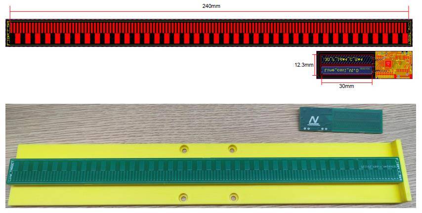
(1) Core design: The sensing coil (including the PCB stator) serves as the moving end, while the metal target plate (conductive material) is fixed; displacement detection is achieved through changes in the electromagnetic field as the coil moves;
(2) Key layout: The target plate layout dimensions are 240 mm long; the coil is 30 mm long and 12.3 mm wide.
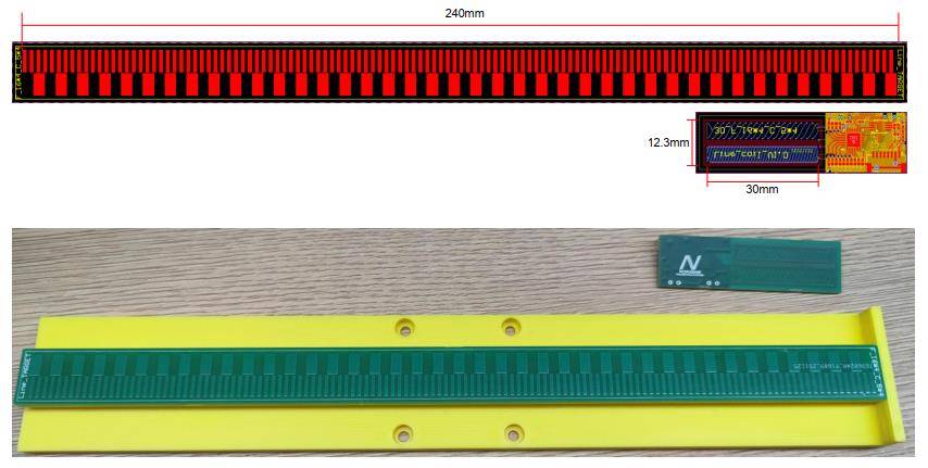

Test fixture
(3) Test results: For the 3 cm travel test, the error range was roughly maintained from -0.005 mm to 0.005 mm, with the error controlled at the micrometer level. For short travel, the MT6901 linear displacement measurement error is extremely small, and stability is excellent.

The 10 cm travel test results show the error remains between -0.01 mm and 0.02 mm. The error increases slightly for longer travel but still maintains high accuracy.

III. Product Introduction
The MT6901 is a high-speed, high-precision angle encoder chip based on eddy-current sensing technology, launched by Magtron Microelectronics (now part of NOVOSENSE). The position detection system consists of a stator, a rotor, and the chip application circuit. The stator has excitation coils, receiving coils, and their associated chips, while the rotor has a specific shape matched to the coils. It has a built-in EEPROM programmable from 3.3 V to 5.0 V, integrates multiple diagnostics such as excitation coil disconnection and received signal amplitude out of range, and can operate normally from -40°C to 125°C.
The MT6901 supports incremental ABZ, incremental UVW, PWM, UART, and 4-wire SPI outputs. The incremental ABZ output supports 1 to 16,384 pulses per revolution and is programmable; the motor commutation position signal UVW output supports 1 to 16 pole pairs and is programmable; the 4-wire SPI interface can output 21-bit angle data, and the single-wire PWM output can also provide a 12-bit resolution absolute position signal for ease of use; the UART communication interface resolution can be configured as 17 or 23 bits, and the communication baud rate can be configured as 2.5 Mbps or 4.0 Mbps, allowing direct connection to a servo system for angle closed-loop control.
The MT6901 provides a client-side self-calibration mode with no data interaction and automatic compensation calculation. Through this self-calibration mode, various nonlinearities caused by eccentricity, tilt, and other factors between the coils and rotor can be compensated, achieving linearity (INL) of < ±0.02°.
Core Parameter Table
| Parameter Category | Specification Details |
| Accuracy Specifications | Simple self-calibration INL ±0.1°, constant-speed self-calibration INL ±0.02°, NLC calibration INL <0.01°; hysteresis 0–0.176°, programmable |
| Dynamic Performance | Maximum speed 12000 RPM, typical system delay 10 μs, typical step response time 250 μs |
| Power Supply and Power Consumption | Supply voltage 3.0–5.5 V, typical operating current 33.8 mA; typical power-on ready time 5 ms |
| Reliability Specifications | ESD protection: HBM ±4 kV, CDM ±1 kV; supports fault diagnostics such as excitation coil open circuit and signal amplitude out of range |
| Package and Operating Temperature | QFN 5×5 package; operates normally from -40°C to 125°C |
For more information about the MT6901 or to request samples, please contact the official authorized distributor: sales@chiplinkstech.com (email); WeChat Official Account: Zhilianwei - Motor Control Chips, providing product selection services and technical support.

Sample Request Attached

WeChat Official Account