
In 2026, photovoltaics, AI servers, and new energy vehicles—three industries—are almost all doing the same thing: stepping up voltage.
In the PV energy storage field, the DC bus voltage of string inverters is migrating from 1000 V to 1500 V to reduce cable losses in long-distance DC transmission. In the AI server field, Nvidia released a technical white paper in April 2026, '800 VDC Architecture for Next-Generation AI Infrastructure,' setting 800 V HVDC (high-voltage direct current) as the standard power architecture for next-generation data centers; the B200 GPU has reached 1000 W per card, and the B300 series is about 1400 W. In the new energy vehicle field, the 800 V platform has spread from Porsche Taycan's early trial to mainstream brands such as BYD, XPeng, and Zeekr, and the penetration rate of SiC in 800 V platform main-drive inverters is expected to grow from 12% in 2024 to more than 35% in 2026.
The three tracks have different reasons for stepping up voltage, but there is only one underlying physical logic. This logic supports power architectures moving toward higher voltage, and the selection rules for power devices are also changing.
1. P=I²R: The Physical Logic of Higher Voltage
In power transmission, conduction loss equals current squared times resistance: P = I² × R. Current is the squared term; when voltage doubles, current halves, and conduction loss drops to one quarter of its original value.
This formula reflects why higher voltage is needed in the three scenarios:
Photovoltaics. DC cables from modules to inverters can be tens of meters or even over 100 meters long. Under a 1000V bus, a 30kW string carries about 30A, and cable resistance losses accumulate into considerable economic loss in large plants. After raising the voltage to 1500V, the current at the same power drops to 20A, and I²R losses fall by more than 50%. For a plant with a 25-year design life, this figure is directly reflected in the return on investment.
AI servers. NVIDIA B200 single-card power consumption is 1000W, and the B300 series is about 1400W. Under the traditional 54V architecture, 1000W per card means a bus current exceeding 18A, and an 8-GPU server node has a bus current approaching 150A. More importantly, traditional AC power supply requires multiple stages of AC/DC conversion through transformers, UPS, server power supplies, and other stages, with cumulative energy loss of about 6%–9%. The 800V HVDC architecture compresses these conversion stages, delivering overall efficiency 3–5 percentage points higher than the traditional UPS architecture, reducing copper cable usage by more than 45%, and saving 30% space (Source: NVIDIA 800V HVDC Technical Whitepaper, April 2026). In 2026, the total electricity consumption of AI-optimized servers worldwide is expected to reach 175 TWh, up 84% year-on-year (Source: Xinyu Ai Shuma, July 2026).
New energy vehicles. Under a 400V platform, 350kW fast charging requires about 875A (calculated at the nominal 400V; battery voltage can reach about 450V when fully charged, giving an actual current of about 778A, but at low SOC it is still close to 875A). Current at this level is a huge challenge for cable cross-sectional area, connector current-carrying capability, and thermal design, and the charging cable becomes so thick and heavy that it is difficult to operate with one hand. Under an 800V platform, the charging current for the same power halves to 437A, cable cross-sectional area and weight drop significantly, and power devices at the charging pile end have more margin. Nationwide public ultra-fast charging piles (≥480kW) have exceeded 80,000 units, with year-on-year growth of more than 200%.
The numbers differ across the three scenarios, but the reasoning chain is the same: step up voltage → step down current → reduce losses. But to implement this logic, the power devices themselves must first withstand higher voltages.
II. Photovoltaics: Modular Selection Under a 1500V Bus
In photovoltaic and energy storage systems, the 1500V bus runs through three types of power conversion stages: string inverters (DC→AC), energy storage PCS (bidirectional DC↔AC), and DC-DC boost. The three have the same voltage withstand requirements, but their topologies and power flow directions differ, so selection has different focuses.
String inverters place stringent requirements on device reliability: outdoor operation, ambient temperature from -40°C to above 65°C, a 25-year design life, and a cumulative device operating time requirement exceeding 100,000 hours.
As the bus rises from 1000V to 1500V, there are two changes in selection logic.
First, the voltage withstand threshold has increased.At a 1500 V bus voltage, the choice of topology directly affects the device voltage rating. In a two-level topology, the switches bear the full bus voltage and require 1700 V devices, making cost and device availability unfavorable. The outer switches of a T-type three-level topology also bear the full bus voltage and require 1700 V devices, which is less economical than the NPC topology in 1500 V systems. Therefore, mainstream string inverters adopt NPC/ANPC/INPC three-level topologies, in which each switch bears only half the bus voltage, i.e., a 750 V static voltage. After switching spikes are added, the actual stress can exceed 850 V, corresponding to 1200 V devices. This is the mainstream voltage-rating selection for 1500 V photovoltaic systems. Under a 1000 V bus, using 650 V devices in an NPC three-level topology is the conventional solution, with each switch bearing 500 V.
Second, demand for modularization is rising.As string inverter power evolves from 100 kW to 250 kW+, heat dissipation and current sharing of paralleled discrete devices become bottlenecks, and integrated power modules are becoming a trend. The following uses the three-level module products from Jinlan Semiconductor (a wholly owned subsidiary of NCE Power) as an example:
| Model | Voltage/Current | Power Rating | Technical Features | Application Scenarios |
| JL3T400V120SE3G7SS | 1200V/400A | 125kW | Gen.7 IGBT + SiC SBD, three-level | String PV inverter |
| JL3I600V110SE3E7SS | 1100V/600A | 215kW | Si3N4 AMB substrate, three-level | Energy storage PCS (1500 V system) |
JL3T400V120SE3G7SSA hybrid solution using Gen.7 IGBTs as main switches and SiC SBDs as freewheeling diodes. The IGBT has low conduction loss, and the SiC SBD has extremely low reverse recovery charge; the combination balances efficiency and cost, making it a common technical route for current 1500 V PV inverters. Compared with a pure IGBT solution, the hybrid solution can improve overall system efficiency by 0.5%–1% while retaining the original IGBT design framework, so modification costs remain controllable.
1100 VJL3I600V110SE3E7SS, mainly targeting more cost-sensitiveEnergy Storage Projects. The key difference between energy storage PCS and PV inverters is the need for bidirectional power flow (charging and discharging). The device body diode performs the freewheeling function during reverse conduction, placing higher requirements on reverse recovery characteristics. Therefore, energy storage PCS tend to use SiC MOSFETs or fast-recovery IGBTs. This module uses a Si3N4 AMB substrate; compared with conventional Al₂O₃ substrates, thermal resistance is reduced by more than 30% (Si3N4 thermal conductivity is about 4 times that of Al₂O₃), and thermal shock resistance is greatly improved, making it suitable for the frequent charging/discharging conditions of energy storage PCS.
Forthe DC-DC boost stage, 1200V SiC MOSFETs can replace conventional IGBTs to achieve higher switching frequency and efficiency. For example, NCE Power'sNCES120P020T4model, 1200V/20mΩ/182nC/TO-247-4L. The all-SiC solution (all three-level bridge legs use 1200V SiC MOSFETs) reduces switching losses by more than 70% compared with IGBTs, supports higher switching frequencies, can reduce the size of passive components such as inductors and capacitors, and is suitable for high-end models pursuing ultimate efficiency; however, the cost premium is relatively high, and it is currently mainly used in flagship products.
In lower-power or cost-sensitive scenarios,1200V discrete IGBTsThis is a supplement to the module solution. NCE Power's 1200V IGBTs cover six series—B/L/U/V/W/H—with currents from 15 to 100 A. Selection by switching frequency: the B series is suitable for low-frequency, high-power applications (1–20 kHz); the U/V/W series are suitable for medium-to-high frequencies (10–40 kHz); the L series is a low-VCE(sat) type (1.5 V), suitable for low-frequency applications sensitive to conduction loss.
III. AI Servers: SiC Device Selection Under the 800V HVDC Architecture
The power supply chain of AI servers has the most conversion stages and the highest power density requirements among the three scenarios. From the grid to the GPU, it goes through multiple stages such as rectification, isolated DC-DC, bus conversion, and VRM.
Taking NVIDIA's 800V HVDC architecture as an example, its core change is to convert AC power once at the data center level to 800V DC, distribute it to racks via a DC bus, then step it down to 48V through rack-level isolated DC-DC (IBC), and finally supply the GPU through board-level VRM. The high-voltage trend mainly affects two stages: front-end rectification and isolated DC-DC.
Front-End RectificationIt uses a T-type NPC three-level single-stage three-phase boost rectifier, replacing the server-side PFC circuit in traditional architectures. The voltage stress distribution in the T-type NPC topology is asymmetric: the outer switch, when turned off, withstands the full bus voltage of 800V; after adding switching spikes, the actual stress can reach more than 900V, requiring 1200V SiC MOSFETs. The inner switch withstands half the bus voltage, i.e., 400V, so 750V SiC MOSFETs can meet the voltage withstand requirement. In traditional 54V/48V architectures, the PFC output is about 400V DC, and 650V superjunction MOSFETs are sufficient; 800V HVDC doubles the rectified output voltage, so the voltage rating threshold for the outer switch increases accordingly to 1200V.
Primary-side switches of the isolated DC-DC (IBC, 800V→48V)Voltage stress depends on the topology design: in a full-bridge topology, it withstands over 800 V and requires 1200 V SiC MOSFETs; in a half-bridge topology, it withstands 400 V, so 750 V SiC MOSFETs can be selected. SiC's wide-bandgap characteristics provide a high critical electric field and high thermal conductivity; on-resistance and switching losses are far lower than those of silicon devices, and high-temperature performance is also better.
| Model | Voltage Rating | RDS(on) | Qg | Package | Positioning |
| NCES120P020T4 | 1200V | 20mΩ | 182nC | TO-247-4L | T-Type NPC Outer Switch / IBC Full-Bridge Primary |
| NCES075P025T4 | 750V | 25mΩ | 102nC | TO-247-4L | T-Type NPC Inner Switch / IBC Half-Bridge Primary |
NCES120P020T4Used for T-type NPC outer switches and also suitable for the primary side of IBC full-bridge topologies. The 20 mΩ on-resistance keeps conduction losses controllable at high power, and the 182 nC gate charge keeps switching losses controllable in the tens of kHz to hundreds of kHz range. The four-pin package (Kelvin source) reduces gate-drive loop inductance and is suitable for high-frequency operation.
NCES075P025T4For the inner switches of a T-type NPC (400V stress), and also suitable for the primary side of an IBC half-bridge topology. The 25mΩ on-resistance delivers good efficiency at medium power levels.
IV. New Energy Vehicles: Automotive-Grade Selection for 800V Platforms
The requirements of 800V platforms in new energy vehicles for power devices mainly fall into two dimensions: voltage rating and automotive-grade consistency.
In terms of voltage rating,Under an 800V battery bus, the switches in the two-level topology of the main traction inverter must withstand the full bus voltage plus switching ripple, requiring 1200V devices to provide sufficient margin. Vehicle main traction drives commonly adopt a two-level scheme to simplify control and reduce cost.
In terms of automotive-grade consistency,The main traction inverter is a safety-critical component, so devices must pass automotive-grade qualifications such as temperature cycling (-55°C to 150°C), HTRB (1000 hours), and H3TRB (1000 hours). In mass production, it is further required that the parameter spread of every batch and every device be controlled within a very narrow range, ensuring that every device actually delivered has reliability consistent with the qualified samples.
1200V SiC MOSFETs are the first choice for 800V main traction drives. The wide-bandgap physical advantages of SiC are irreplaceable in 800V high-voltage main traction drives: the high critical electric field makes the on-resistance of 1200V SiC far lower than that of silicon devices with the same voltage rating; the high thermal conductivity (4.9 W/cm·K, versus 1.5 for silicon) improves heat dissipation efficiency; and the high electron saturation drift velocity supports higher switching frequencies, reducing the volume and cost of the output filter.
For vehicle models still using a 400V platform (currently the market mainstream), IGBT remains the mainstream solution for the main traction inverter. SiC MOSFETs are an upgrade option, with 650 V as a common voltage rating choice; 750 V provides higher voltage margin and is suitable for designs with higher requirements for reliability and efficiency. NCE Power's automotive-grade SiC product line covers two voltage rating tiers, 750 V and 1200 V:
| Model | Voltage Rating | RDS(on) | Package | Applicable Platform |
| NCEAS075P025T4 | 750V | 25mΩ | TO-247-4L | 400V Platform Main Traction |
| NCEAS075P080T4 | 750V | 80mΩ | TO-247-4L | 400V Platform OBC |
| NCEAS120P030T4 | 1200V | 30mΩ | TO-247-4L | 800V Platform Main Traction |
| NCEAS120P080T4 | 1200V | 80mΩ | TO-247-4L | 800V Platform OBC (6.6–22 kW) |
| NCEAS120P160D7 | 1200V | 160mΩ | TO-263-7L | 800V Platform Auxiliary Power Supply |
Note: Some models are in the mass-production introduction phase
In addition to the main drive,OBC and high-voltage DC-DCare also important selection considerations for 800V platforms. 1200V SiC MOSFETs (e.g., NCEAS120P080T4) can support switching frequencies above 100 kHz, reducing magnetic component volume by more than 40%, which helps enable the three-in-one integration of OBC, DC-DC, and PDU.
For cost-sensitive 800V platforms (such as A0/A-segment vehicles), 1200V IGBTs remain the cost-priority solution for main drive inverters, but their efficiency ceiling is lower than that of SiC and their switching frequency is also lower, making them suitable for models with less extreme range and efficiency requirements.
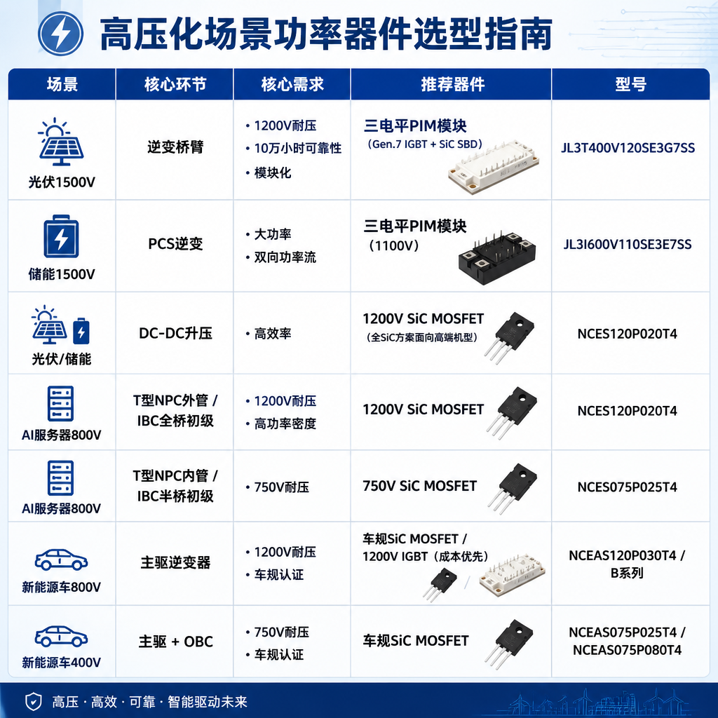
V. Product Selection Overview
| Scenario | Core high-voltage link | Core requirements | Recommended devices | Part number |
| Photovoltaic 1500 V | Inverter bridge arm | 1200 V withstand voltage + 100,000-hour reliability + modularity | Three-level PIM module (Gen.7 IGBT + SiC SBD) | JL3T400V120SE3G7SS |
| 1500V energy storage | PCS inverter | High power + bidirectional power flow | Three-level PIM module (1100V) | JL3I600V110SE3E7SS |
| PV/Energy storage | DC-DC boost | High efficiency | 1200V SiC MOSFET (all-SiC solution for high-end models) | NCES120P020T4 |
| AI server 800V | T-type NPC outer switch / IBC full-bridge primary | 1200V voltage rating + high power density | 1200V SiC MOSFET | NCES120P020T4 |
| AI server 800V | T-type NPC inner switch / IBC half-bridge primary | 750V voltage rating | 750V SiC MOSFET | NCES075P025T4 |
| New energy vehicle 800V | Main Traction Inverter | 1200V Voltage Rating + Automotive-Grade Certification | Automotive-Grade SiC MOSFET / 1200V IGBT (Cost-Priority) | NCEAS120P030T4 / B Series |
| New Energy Vehicle 400V | Main Traction + OBC | 750V Voltage Rating + Automotive-Grade Certification | Automotive-Grade SiC MOSFET | NCEAS075P025T4 / NCEAS075P080T4 |

VI. Conclusion
All three industries are moving toward higher voltages, and the underlying physical logic is the same: step up the voltage, reduce the current, and cut losses. After bus voltages are raised from 1000 V, 54 V, and 400 V to 1500 V, 800 V, and 800 V, respectively, the requirements for power devices differ. 1200 V SiC MOSFETs are used in photovoltaics, AI servers, and automotive applications, but the three scenarios place different emphasis on reliability, efficiency, and quality grade (industrial/automotive).
Higher voltage is not just a change in the bus voltage number; it is also redefining how the value of power devices is evaluated: voltage rating is the entry ticket, while the different weights of loss and reliability in each scenario are further considerations. As the bus voltages of the three tracks converge in the 800 V to 1500 V range, what tests manufacturers is not only whether they have products covering a given voltage class, but also whether they can achieve a thorough balance among loss, reliability, and cost in each segmented scenario.
For more information about NCE Power power devices or to request samples, please contact: sales@chiplinkstech.com; Engineer Chen, 13924675549.
Note: For node-by-node selection across the entire AI server power supply chain, please refer to“From the Grid to the GPU Core: NCE Power Devices Lay Every ‘Brick’ in the AI Server Power Supply Chain”article.

Sample Request Attached

WeChat Official Account