
In a robot factory’s commissioning workshop, engineer Wang is facing a difficult problem: due to tiny deviations in mechanical installation, the newly introduced precision robot has consistently been unable to achieve its calibrated positioning accuracy. A conventional solution would require disassembly and reassembly, which would mean days of schedule delay and tens of thousands of yuan in additional costs. This time, however, it was different—using a rotary encoder equipped with NOVOSENSE’s AMR-based MT6826S chip, a simple self-calibration routine automatically compensated for the tiny mechanical error, avoiding a long schedule delay and extra costs.

1. Functional System Overview of the MT6826S
The MT6826S, which helped engineer Wang solve the difficult problem, is a new-generation high-speed, high-precision angle encoder chip from MagnTek Microelectronics (now part of NOVOSENSE), based on advanced anisotropic magnetoresistance (AMR) technology. Inside the chip, sensing elements formed by two pairs of AMR Wheatstone bridges arranged at 45° to each other change with the direction of the applied magnetic field and output two sinusoidal/cosine analog voltage signals. After amplification in the analog front-end circuit (the “G” block in the figure) and filtering, the signals are sent to an analog-to-digital converter (ADC); the amplified and digitally quantized sine/cosine signals finally enter a digital signal processor (DSP) for compensation, calibration, and angle-solving operations. The resulting absolute digital angle data can be output through SPI or PWM output interfaces, while further signal processing synthesizes the absolute angle into incremental ABZ and UVW outputs. In addition, the system also includes modules such as a low-dropout regulator (LDO), clock oscillator (OSC), and electrically erasable programmable memory (EEPROM).

Chip Functional Block Diagram
Key Parameters Table:
| Operating Voltage | 3.3V~5.0V |
| Operating Temperature | -40℃~125℃ |
| Operating Current | 15–28 mA (typical 22 mA) |
| System Delay (Constant Speed) | 2us~10us |
| Maximum Supported Speed | ≤120,000 rpm |
| ABZ Incremental Output | 1–4096 lines, freely programmable |
| UVW incremental output | 1–16 pole pairs, arbitrarily programmable |
| PWM output | 12bit |
| Absolute angle | 15bit |
| Communication interface | 4-wire SPI |
| Package | TSSOP-16,QFN4×4 |
| INL (typical, self-calibrated) | <±0.1° |
| Alarm function | Overspeed, magnetic field too weak, supply undervoltage |
II. Technical Foundation: AMR Technology
The technical foundation of the MT6826S lies in its unique anisotropic magnetoresistance (AMR) technology, which is fundamentally different from Hall-effect technology: the chip integrates a sensitive element composed of two pairs of AMR Wheatstone bridges arranged at 45° to each other. Because AMR devices operate in the saturation region when used for angle measurement applications (the saturation magnetic field is 300 Gauss), in actual operation the chip responds only to changes in the direction of the magnetic field parallel to the chip surface, and is independent of magnetic field strength (30–1000 mT). Therefore, during use, the MT6826S has relatively low requirements on the machining error of the magnet itself and on the mounting distance error between the magnet and the chip, reducing the difficulty of system installation:
| Magnet machining error | No need to strictly control the uniformity of the magnet's magnetic field |
| Installation gap (AG) | The distance between the chip and the magnet can be adjusted within 1.0–3.0 mm (1.0 mm is recommended for best performance) |
| Eccentricity deviation (DISP) | When the deviation between the magnet center and the chip sensing center is ≤0.3 mm, errors can still be compensated through self-calibration. |
| Recommended magnet specifications | 1 pole pair, radially magnetized cylindrical magnet, diameter 10 mm, thickness 2.5 mm (can effectively reduce nonlinearity error) |
A vivid analogy can help understand this: a Hall sensor is like “measuring length with a rubber band”—changes in tension (magnetic field strength) cause measurement deviations; while the MT6826S is like “measuring length with a rigid ruler”—as long as the direction (magnetic field direction) is accurate, the result is unaffected by external force (magnetic field strength), significantly improving stability.
3. Core Innovation: Intelligent Self-Calibration Technology
The core performance improvement of the MT6826S lies in providing a convenient customer-side self-calibration mode. This technology is not simple “error correction” but a standardized, monitorable closed-loop calibration scheme. Through the self-calibration mode, various nonlinear errors caused by non-ideal magnets and structural installation deviations can be automatically compensated, greatly improving the INL characteristic and ultimately achieving INL of <±0.07°. Compared with the “threading a needle under a microscope” calibration of traditional encoders, its operation process is simpler:
1. Pre-Calibration Preparation
Configure the speed range: Write to the AUTO_CAL_FREQ register via SPI to select the self-calibration speed range (default 400–800 RPM; optional 25–6400 RPM);
System status requirements: Ensure that the magnet and chip are securely mounted and free from vibration interference, so that the system can run smoothly at a constant speed (speed fluctuation ≤ ±5%).
2. Calibration Execution Procedure
Start calibration: Pull the CAL_EN pin (TSSOP-16 pin 4; QFN4×4 pin 20) high (or write 0x5E to register 0x155 via SPI); the chip enters self-calibration mode;
Continuous operation: Keep the system running at a constant speed for at least 18 revolutions (to ensure full angular coverage and collect sufficient data);
Status monitoring: Determine calibration progress in two ways: PWM output: A duty cycle of 50% indicates calibration in progress, 25% indicates calibration failure, and >99% indicates calibration success; SPI register: Read 0x113 [7:6]; 01 = in progress, 10 = failed, 11 = successful.
3. Post-Calibration Operations
After successful calibration, the chip must be powered off and restarted to ensure that the calibration parameters (stored in EEPROM) take effect; if calibration fails, check the installation gap, eccentricity deviation, or speed stability, and repeat the calibration procedure.
In the world of precision control, a tiny difference often determines the success or failure of an entire system. The automatic calibration function of the MT6826S acts like "a precision instrument," automatically identifying and compensating for errors in the system. It not only achieves high linearity but also greatly simplifies installation and commissioning.
IV. Core Performance Analysis
The MT6826S delivers outstanding performance metrics and can be regarded as a benchmark product in the field of angle measurement.
1. Ultra-High Resolution and Accuracy
The MT6826S provides a 15-bit absolute angle output, and 32,768 position points can be read via a 4-wire SPI interface. The ultra-high resolution ensures that even under extremely small angle changes, the chip can accurately capture and feed back position information. In terms of accuracy, through the self-calibration mode, INL can reach <±0.07°, meeting the stringent requirements of precision motion control.
2. High-Speed Response Capability
In high-speed application scenarios, the MT6826S also performs excellently. It supports a maximum speed of ≤120,000 RPM. When the ABZ resolution is 4096 pulses/revolution, it supports up to 30,000 RPM (to avoid AB signal frequency exceeding 2 MHz, which would cause INL degradation); it features low latency, with system latency of only 2–10 µs and a step response time of 100 µs. This high-speed response characteristic makes the MT6826S very suitable for high-dynamic applications requiring real-time position feedback, such as servo motors and robot joints.
3. Multiple Output Modes
In terms of interfaces, the MT6826S is like a diplomat fluent in multiple languages, able to communicate seamlessly with different types of systems:
Incremental signal output: supports industrial-standard ABZ signals (programmable from 1 to 4096 lines, up to 16384 steps per revolution) and can directly replace traditional optical encoders; supports UVW commutation signals dedicated to motor drive (programmable from 1 to 16 pole pairs), meeting the commutation requirements of brushless motors.
Absolute angle output: A 4-wire SPI interface reads 15-bit absolute angle data for applications that need real-time absolute position, such as valve control and actuator positioning. The single-wire PWM interface has 12-bit resolution and a selectable frequency of 497/994 Hz. Each PWM frame starts with 16 high clock periods, uses 4095 clock periods for data, and ends with 8 low clock periods. The PWM output can report angle or speed, simplifying circuit design.
The multi-interface design allows system engineers to flexibly choose the communication method best suited to their system, greatly simplifying circuit design.
4. Rugged and Durable Industrial-Grade Quality
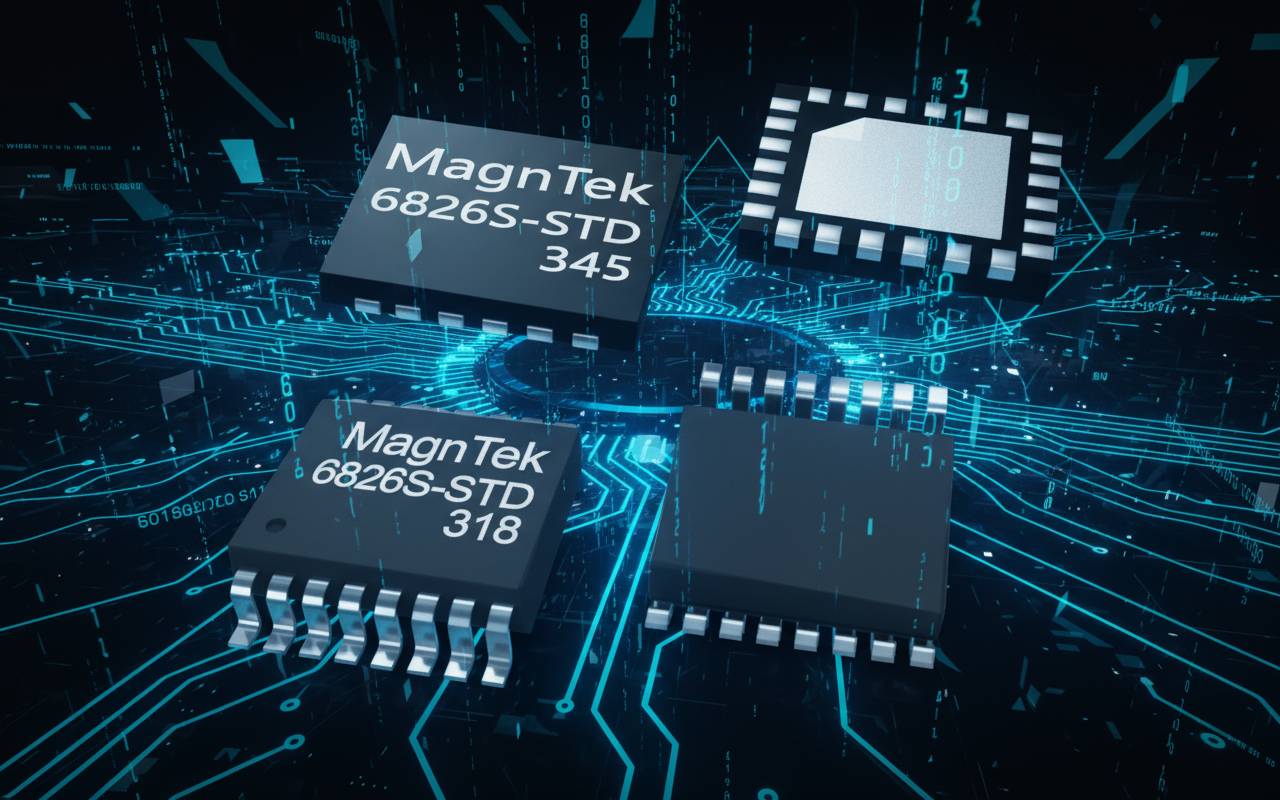
The MT6826S design fully considers complex and extreme environmental factors in practical applications, and it offers the ruggedness and reliability of industrial-grade products: the chip operates over a wide temperature range of -40°C to 125°C, adapting to extreme temperature working environments; ESD protection (HBM ±8 kV, CDM ±1.5 kV) and latch-up immunity of ±100 mA make it suitable for electromagnetically complex industrial environments; it is available in two package options, TSSOP-16 (6.5 mm × 4.4 mm) and QFN4×4 (4 mm × 4 mm), meeting installation needs under different space constraints.

MT6826S package appearance diagram
V. Application Scenarios: Creating Value Across Multiple Fields
With its outstanding performance, the MT6826S demonstrates broad application prospects in multiple high-end fields.
Motor control: In servo motor control and brushless DC motor control, the high precision and high-speed response of the MT6826S provide accurate position feedback for motors, making it key to achieving precise motion control. For closed-loop stepper motor control applications, the chip's high resolution ensures smooth low-speed operation and precise positioning.
Industrial automation: In industrial robotics, the MT6826S can be used for joint angle measurement, and its rugged magnetic structure is unaffected by harsh industrial environments such as oil contamination and dust. As an absolute angular position sensor, it also performs well in scenarios such as valve control and actuator positioning.
Replacement for optical encoders: The MT6826S offers a more reliable and more economical solution that can directly replace traditional optical encoders. Its magnetic sensing principle is unaffected by environmental contamination, provides longer life, and requires lower maintenance costs, making it especially suitable for harsh environments.
VI. Conclusion
In an era pursuing precision and efficiency, precision measurement takes countless forms, while intelligent sensing is one in a million. With its unique technological advantages and innovative user experience, the MT6826S quietly plays its role in the elegant movements of countless robotic arms and the precise operation of numerous smart devices. It solves not only the accuracy issue of angle measurement, but also, through its self-calibration technology and rich interface options, makes high-precision measurement simpler and more reliable, injecting new momentum into the field of precision control.
For more information about the MT6826S or to request samples, contact NOVOSENSE's official authorized distributor: sales@chiplinkstech.com, WeChat official account: ZhiLianWei - Motor Control Chips. Product selection services and technical support are available. We look forward to more engineers using the MT6826S to solve precision challenges in practical applications and achieve dual optimization of efficiency and cost.

Appendix: Sample Request

WeChat Official Account