
AN53: TMC4671 PI Tuning
Document Revision V1.2.2 - 2020-Feb-05
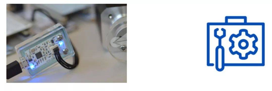
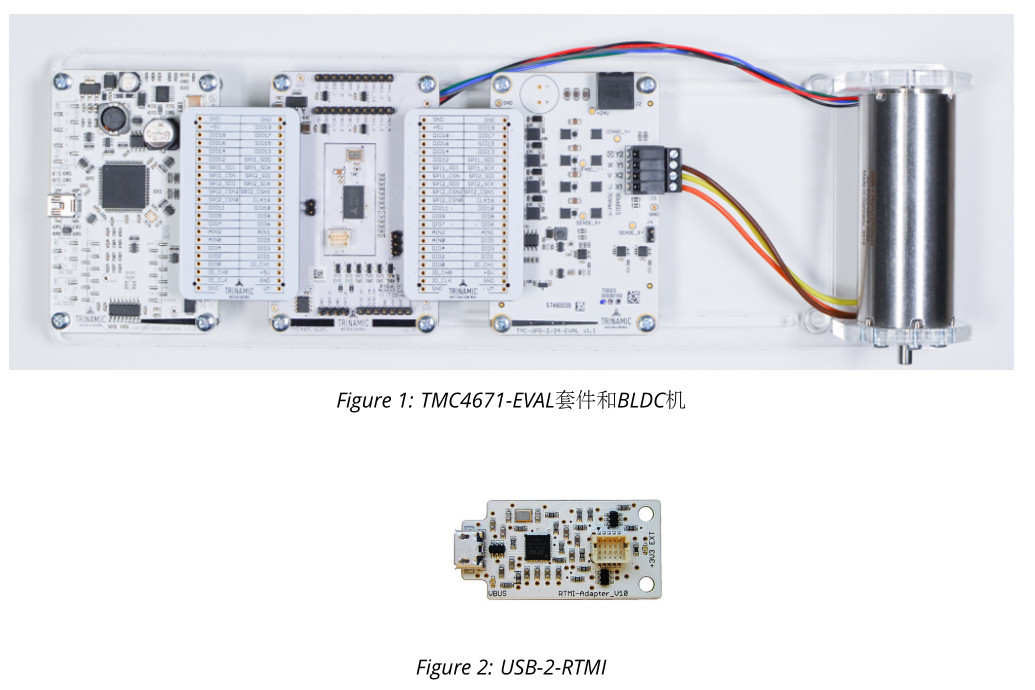
This document describes step by step how to use USB-2-RTMI (RTMI) to tune the TMC4671. The communication converter uses an FTDFT4222H-based high-speed USB-to-SPI bridge. It is USB-powered and has a compact 10-pin connector that matches the RTMI interface pins of the TMC4671-EVAL, and the same pin assignment can be found on the TMC4671 evaluation board. TMCL-IDE provides software tools for tuning different control loops. Therefore, RTMI is the easiest way to tune, monitor, and configure the system.
1 Items used
- Brushless DC servo motor, (e.g. QBL4208-61-04-013-1024-AT)
- TMC4671-EVAL-Kit
- USB-2-RTMI
- TMCL-IDE (3.0.24)
- Power supply (24 V)
- Micro-USB communication cable
- Mini-USB communication cable
mark
2 USB-2-RTMI Driver Installation
Refer to the USB-2-RTMI guide to complete driver installation.
3 Basic Configuration
Before using the debugging tool, the TMC4671 must first be configured (e.g., using the TMC4671 Wizard).
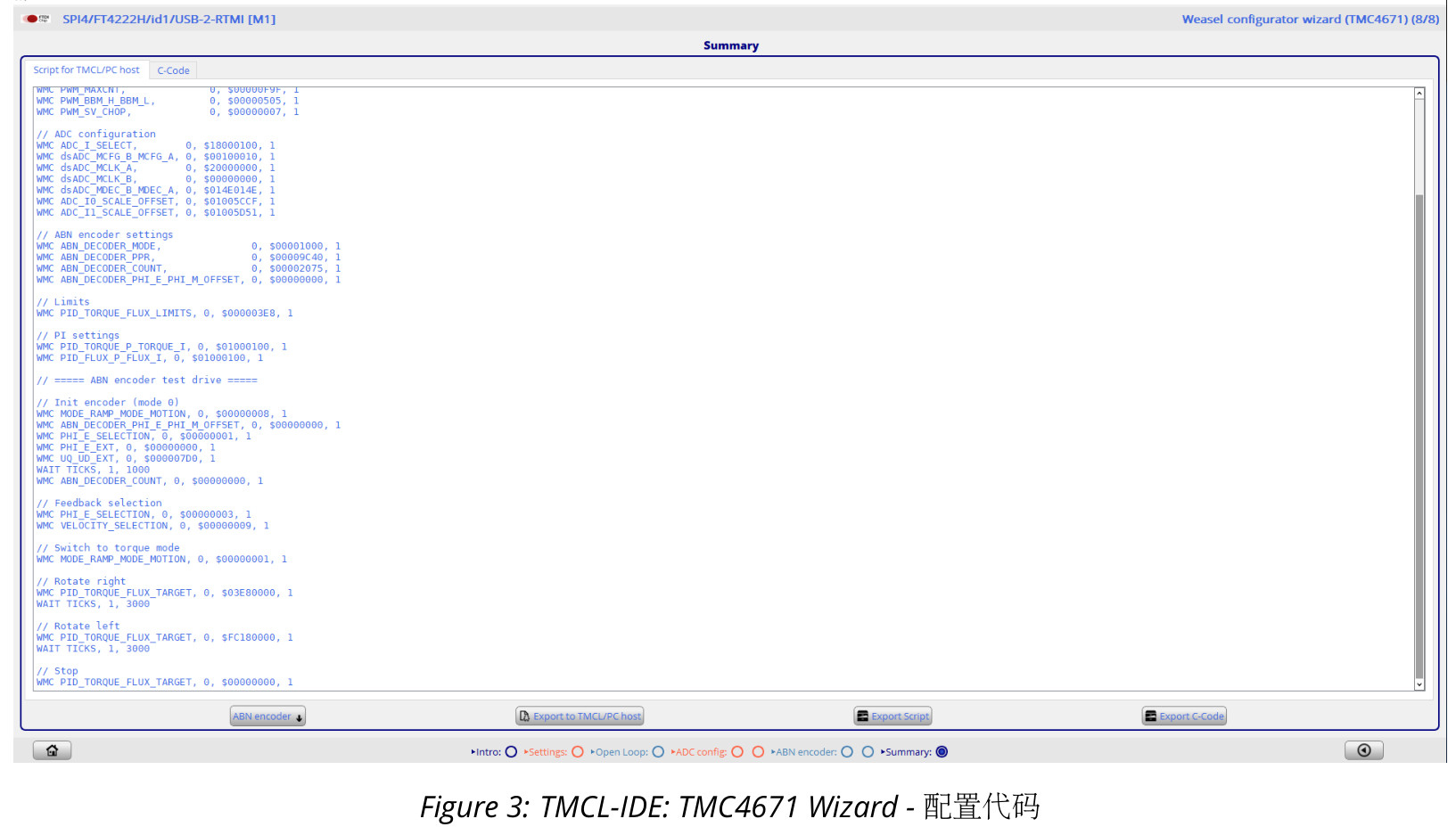
After completing the basic parameter configuration, it can be saved as C code or a .tpc script.
- In the Summary, select ABN encoder.
- Use Export Script to export the script.
4 Tuning
4.1 Overview
The TMC4671 supports three main operating modes, which require PI configuration:
- current/torque mode
- velocity mode
- position mode
Each mode can be tuned for each loop via PI. The following figure provides an overview:
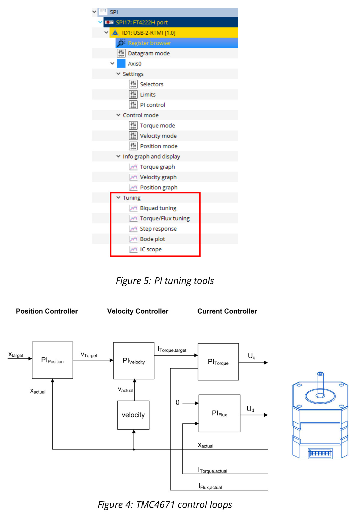
mark
This is a cascaded loop, so the outer loop depends on the tuning of the inner loop. For example, the current loop must be configured before using the speed loop. Software tools are provided for tuning each PI controller. In TMCL-IDE, these tuning tools can be accessed via the Tuning Group. The tuning tools include: - Biquad tuning: used to filter the target value of each loop
- Torque/Flux tuning: identify PI parameters via open-loop step response
- Step response: closed-loop step response for all control loops
- Bode plot: Bode plot for all loops
- IC scope: monitoring, readout of register values and PWM frequency
4.2 Limits
- Before using the tuning tools, it is recommended to set the output voltage to maximum (set PIDOUT_UQ_UD_LIMITS = 32767). For
For step operation, the default value is sufficient. - Set PID_TORQUE_FLUX_LIMITS to the maximum current value allowed in the application.
- Set PID_POSITION_LIMIT_HIGH = 2,147,400,000
- Set PID_POSITION_LIMIT_LOW = -2,147,400,000
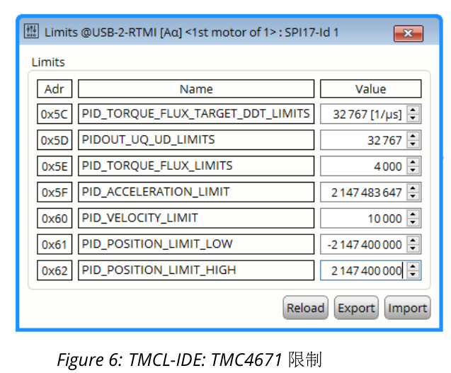
mark
5 Tuning of the current loop
The current loop consists of two control loops: one for torque (current) and the other for flux (current). Both can be adjusted using the RTMI tool in the TorqueFlux / Tuning tool and the Step response tool. The Torque/Flux tool determines the PI parameters in open-loop mode.
5.1 Torque/Flux Tuning Tool (Open Loop)
The Torque Flux tuning tool automatically determines initial PI parameter values by identifying the motor parameters. During this process, a voltage step is set and the current step response is evaluated. Only the flux current is excited to a minimum; there is no motion during this tuning phase. It is recommended to use a PWM frequency of 25 kHz for the best identification results.
-
The TMC4671-EVAL is connected to the RTMI and the PC.
-
Open the “Torque/Flux Tuning Tool”.
-
Click the "Start" button to start tuning
-
Shows the current response to a voltage step and the system identification result
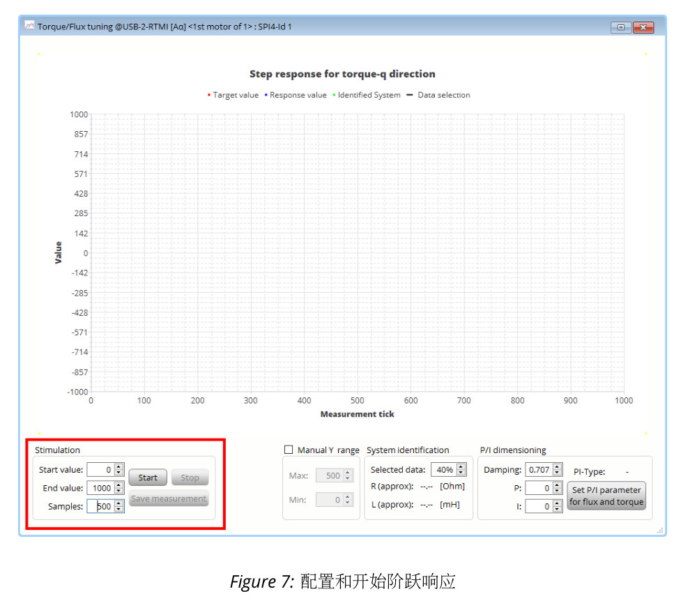
mark 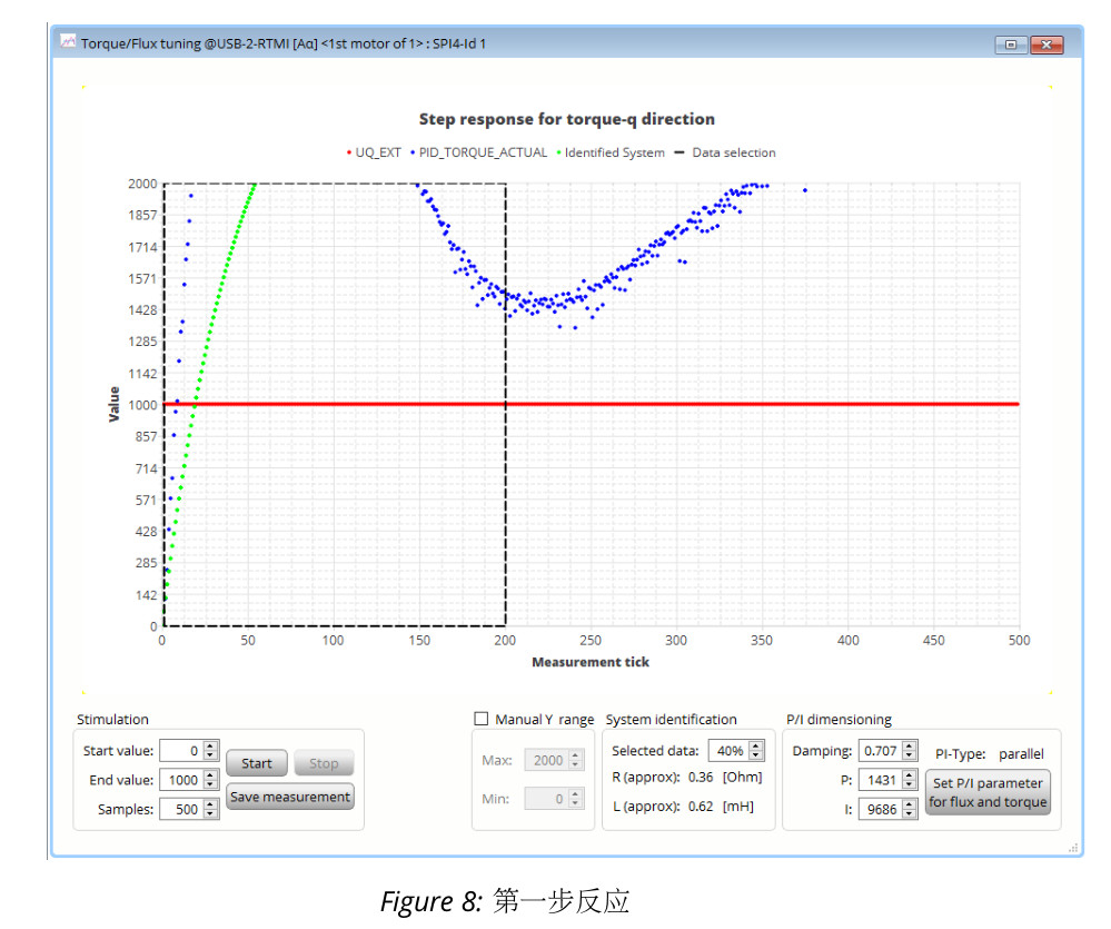
mark -
Check and manually adjust the Y range for a better view
-
Click the "Start" button to re-identify the system; if the motor matches consistently, a better identification result will be provided
-
If necessary, adjust the required computer display window. In most cases, the default settings will provide good results. - The dynamic step response is covered in the identification area (inside the dashed box):
-
The dynamic step response should be covered in the identification area (dashed box)
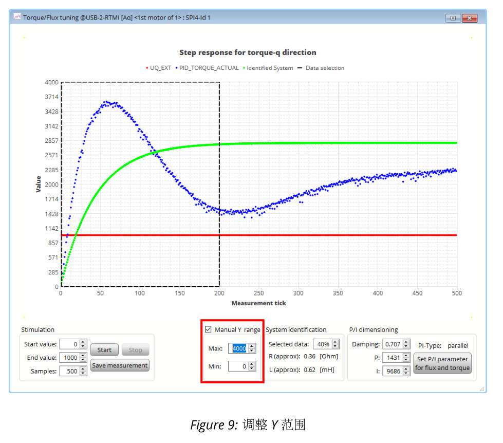
mark 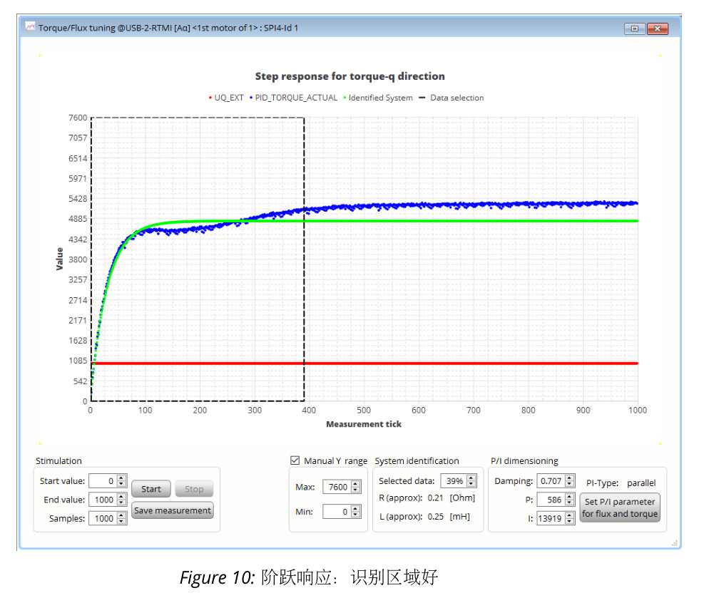
mark -
In Figure 11, the step response is not fully covered. The identification area is too small.
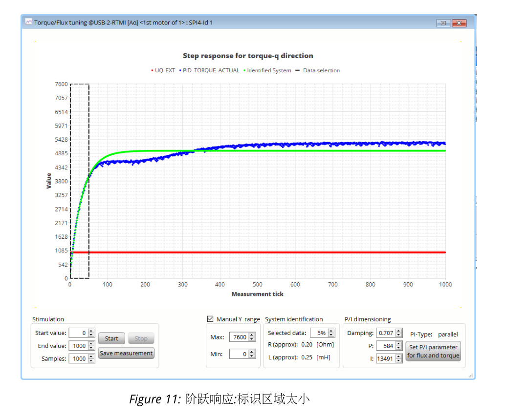
mark -
In Figure 12, the identification area is too large
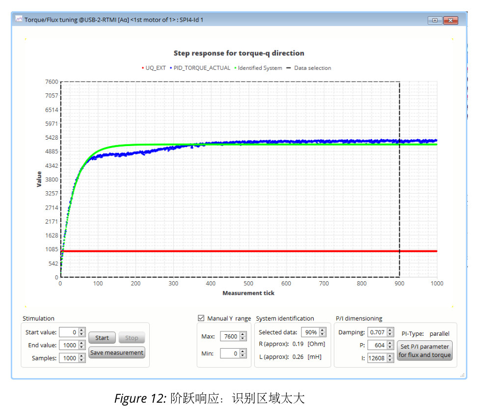
mark
-
-
Write the identified PI values to the current controller
- Use the button below to update the PI values in the current controller
mark - Note: For very high values, the identified I-parameter is displayed as 0. In this case, the I parameter must be set manually (e.g., set to 18000).
- Use the PI control box to confirm the new PI values. The values must be updated using the Reload button.
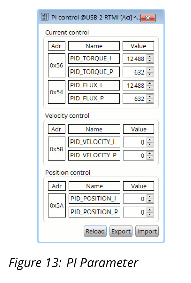
mark
- Use the button below to update the PI values in the current controller
5.2 Step Response Toolbox (Closed Loop)
In the previous step, the PI parameters of the torque/flux current loop were identified in open-loop mode. Now, the step response tool will be used to analyze the closed-loop
behavior.
- Open the Step Response Toolbox
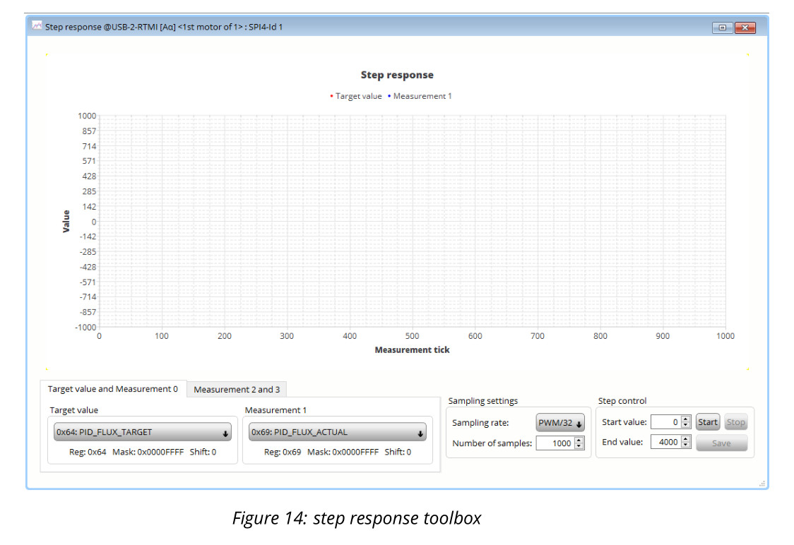
mark - Configure the flux current settings for current control
- Target value: 0x64 PID_FLUX_TARGET
- Measurement 1: 0x69 PID_FLUX_ACTUAL
- Sampling rate: PWM
- Next step
Set Start value = 0
Determine the final flux target current target value (value here is 4000) - Use the Start button to start the step response
- Display the actual current and target current
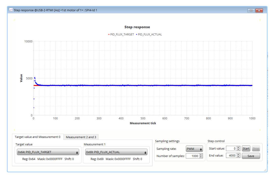
mark - Lower the sampling rate for better results
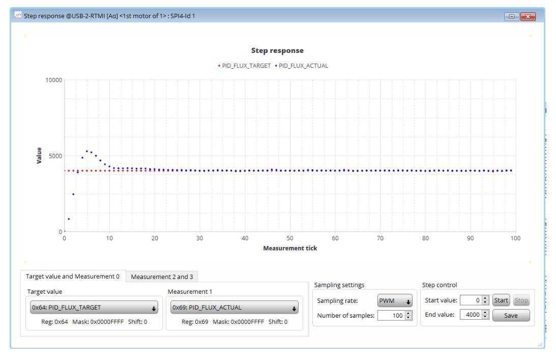
mark - Optimize performance by modifying different P and I values
- Repeat starting from step 2, modifying PID_TORQUE_TARGET and PID_TORQUE_ACTUAL.
5.3 Bode Plot
The Bode plot tool is used to confirm the dynamic performance of the current loop.
-
Open Bode Plot
-
Select 1: torque control loop
-
Start the measurement by clicking the Start button (keep other settings at their default values)
-
Comparison example: the two measurements below show Bode plots with and without tuning using the default PI parameters.
-
Default PI values
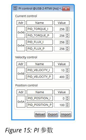
mark 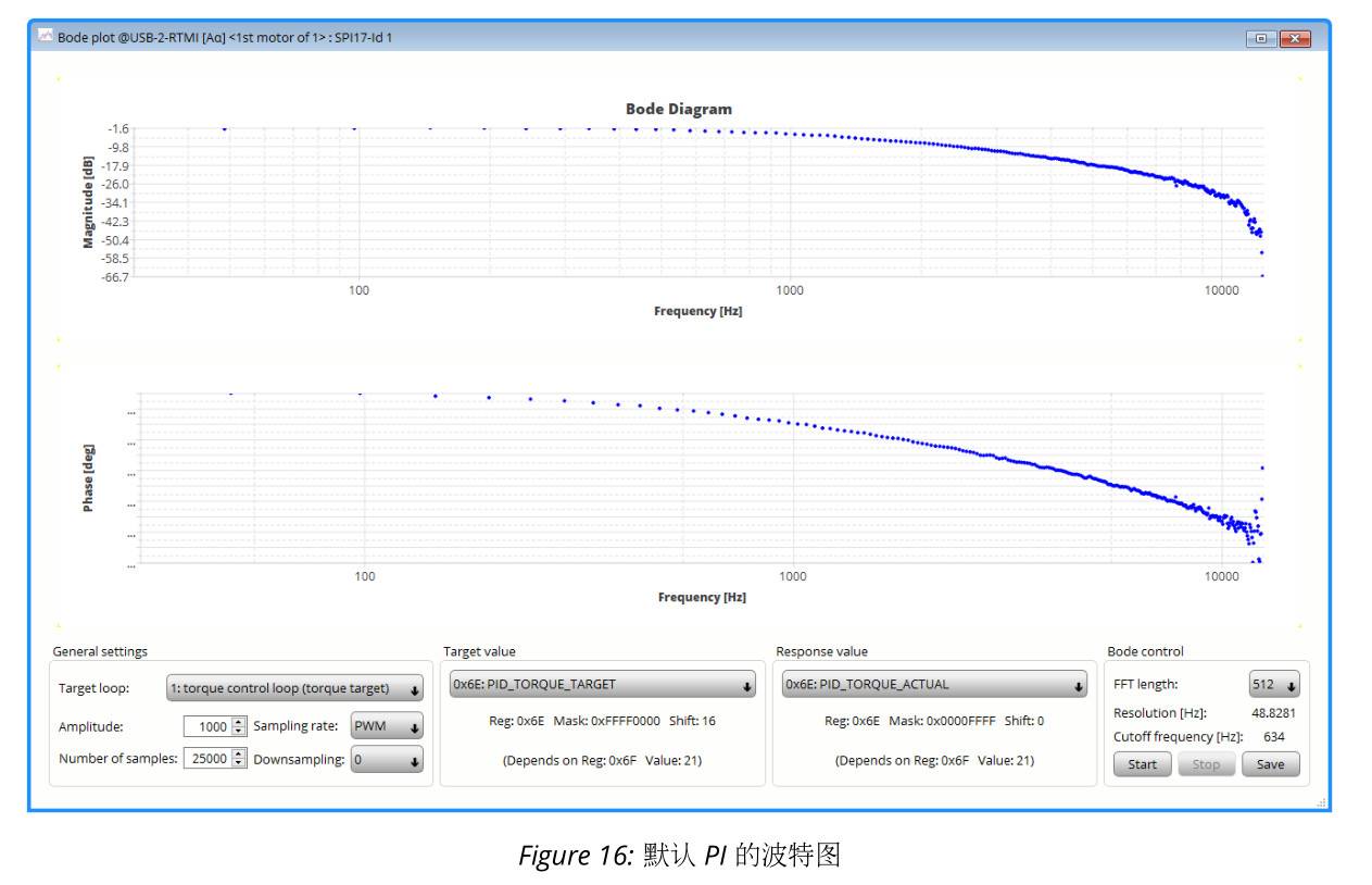
mark -
Adjust PI parameters
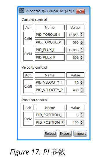
mark 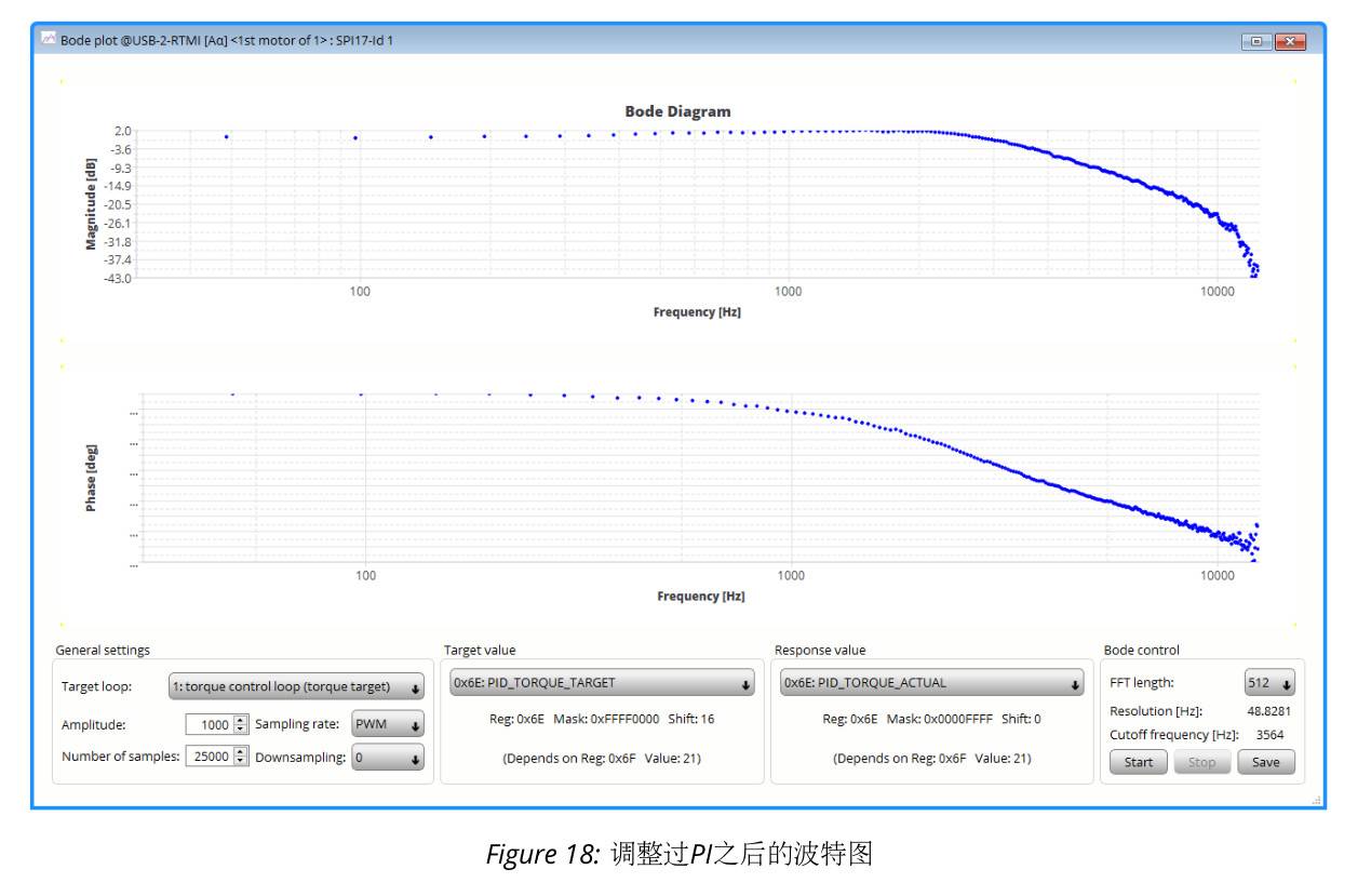
mark -
After tuning the PI, the control system has a higher cutoff frequency and therefore higher dynamic performance.
mark
6 Tuning of the velocity loop
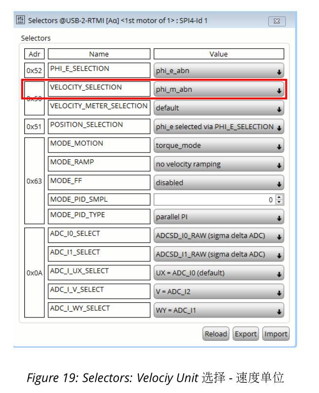
This section describes speed-loop tuning. The prerequisite is that the current loop has already been tuned. To adjust the speed-loop PI parameters, use the step response tool (closed loop).
- For ease of speed unit confirmation, VELOCITY_SELECTION (0x52) in the Selectors toolbox needs to be set from phi_e_selection to phi_m_abn.
- phi_m: The unit for displaying and calculating mechanical speed is RPM (revolutions per minute).
- phi_e: The unit for displaying and calculating electrical speed is electrical cycles.
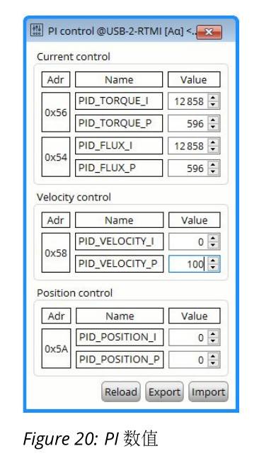
- Set the speed-loop PI parameters.
At the beginning, set a relatively low P value; set I = 0
- 0x58: PID_VELOCITY_I = 0
- 0x58: PID_VELOCITY_P = 100
mark
-
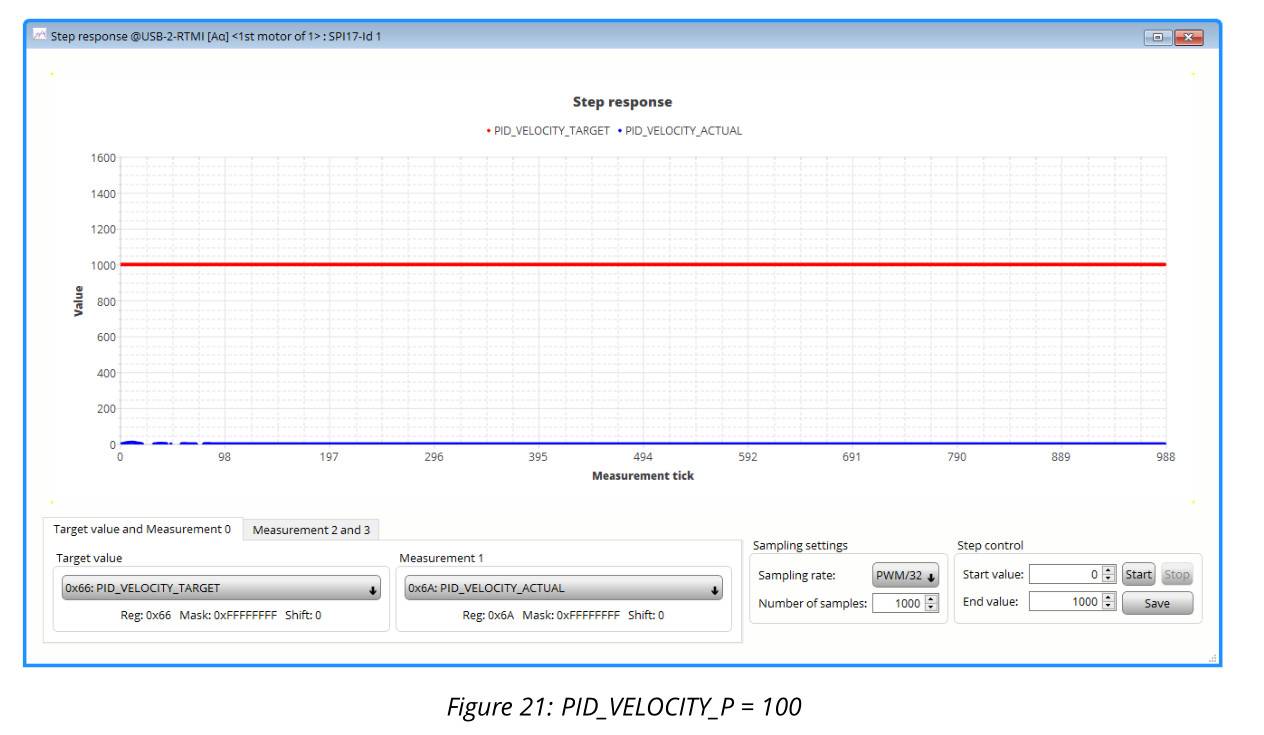
Open the Step Response toolbox
-
Use the step-response example configuration
-
Click the Start button to start the step response
mark -
Gradually increase PID_VELOCITY_P until the actual velocity (PID_VELOCITY_ACTUAL) reaches 50-75%
Target velocity (PID_VELOCITY_TARGET)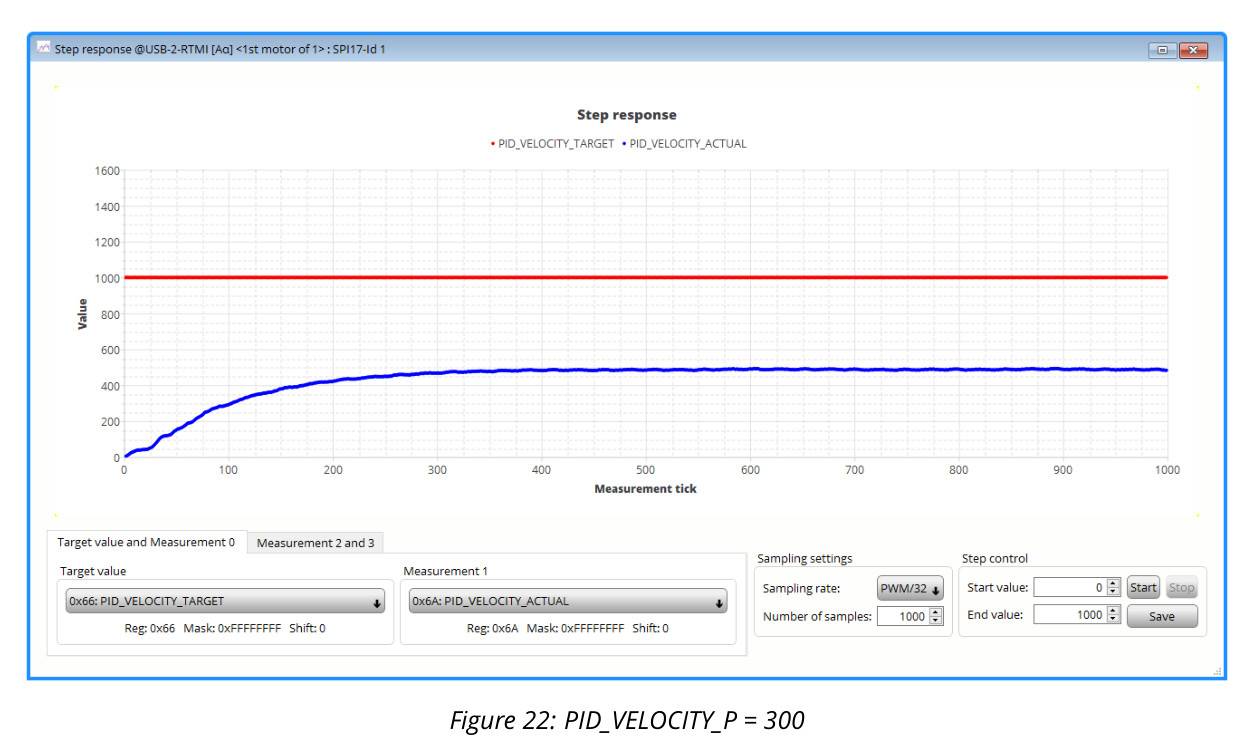
mark 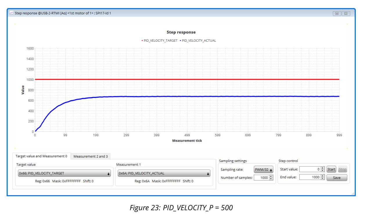
mark -
Increase the PID_VELOCIT_I value until the actual velocity reaches the target velocity
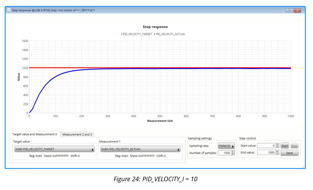
mark 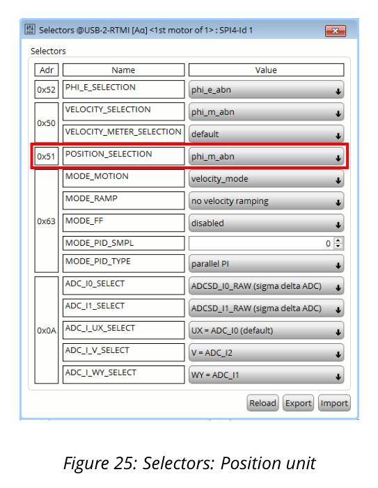
mark
7 Tuning of the position loop
This section describes position loop tuning. Before using the position loop, the current loop and speed loop must first be configured. Use the step response tool for tuning, and then
Use the Landungsbruecke MCU board from the development board kit to improve dynamic performance and accuracy.
7.1 Step Response Tool
-
Set POSITION_SELECTION to phi_m_abn
Therefore, the motor has 65535 counts per revolution. -
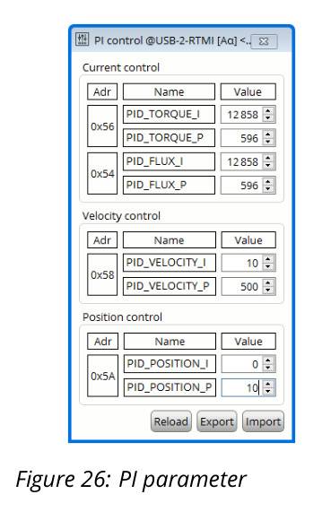
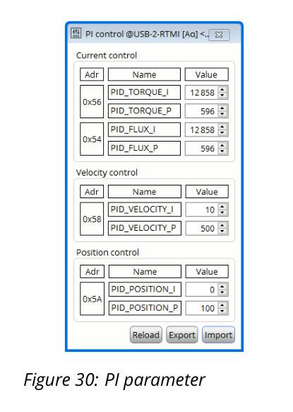
Set the initial values of the PI position controller
- PID_POSITION_I = 0 (for most setups, it is recommended to set this to 0)
- PID_POSITION_P = 10
mark
-
Open the step response tool
-
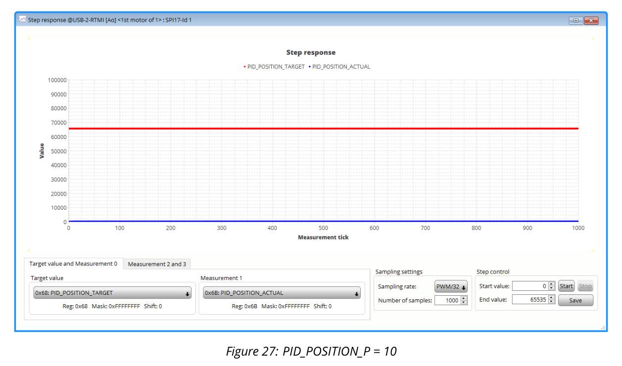
Click the Start button to start the step response. The motor will move back and forth to the end value. Here, this is 1 revolution.
-
When PID_POSITION_P = 10, the motor does not move.
mark -
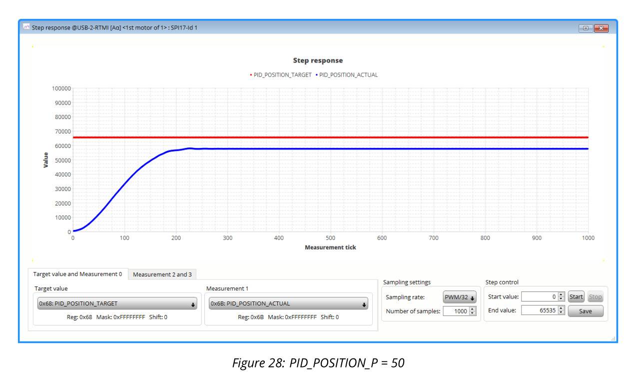
Increase the proportional value P: PID_POSITION_P = 50
mark -
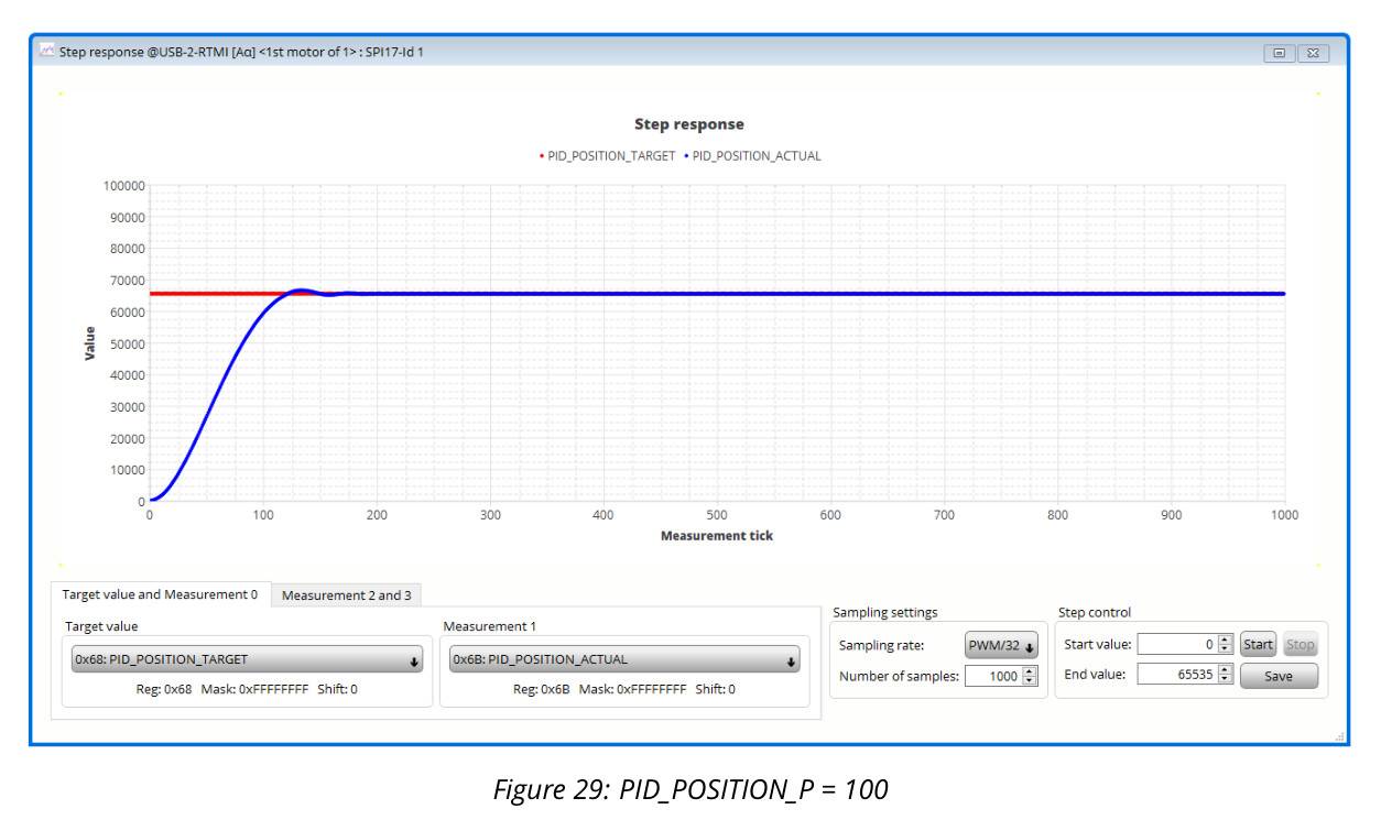
Increase the proportional parameter P value: PID_POSITION_P = 100
mark -
Adjusted PI configuration.
mark
7.2 Motion Controller
The MUC board Landungsbrücke in the development board kit has a trapezoidal ramp generator and can be used together with the TMC4671-EVAL. TMC4671 chip
does not integrate motion control functions.
1. 通过 Mini USB 将MUC板 Landungsbruecke 连接到电脑
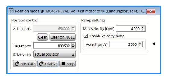
2. In the Landungsbruecke dialog box (USB-2-RTMI unavailable), open the position mode toolbox.
3. Enable the velocity control curve and acceleration limit.
-
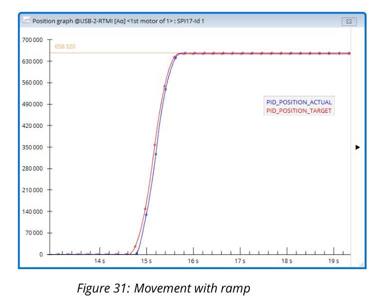
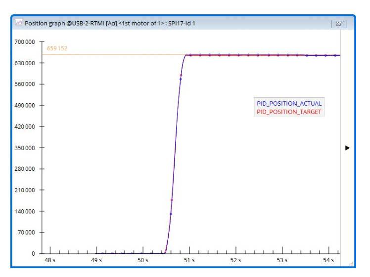
In the position control toolbox (position mode toolbox), control the motor to rotate 10 revolutions.
- Clear the position value
- Set target position Target pos. = 655350
- Click the Absolute button to start motor motion
mark
-
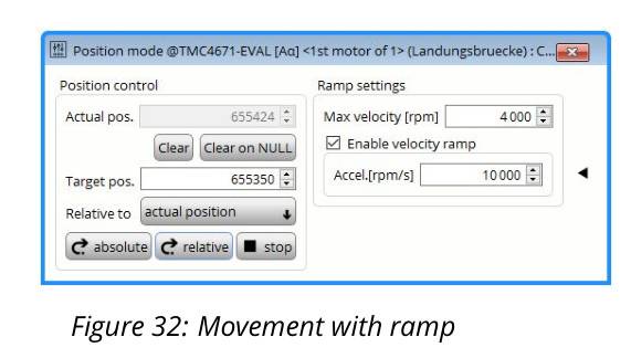
Increase deceleration
mark -
Use motion control to repeat 10 revolutions while increasing the deceleration parameter; PI parameters can also be adjusted at the same time:
mark -
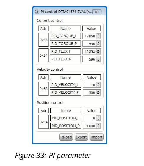
Adjust the PI configuration after adding the motion control function
mark -
Select the Export option to save the PI configuration
8 Summary
The RTMI communication interface provides a powerful option for debugging the TMC4671 chip. Fast real-time access to the chip can be used to debug and monitor each loop. TMCL-IDE provides ready-made software tools for system development. For more information about the TMC4671 and how to use it, please refer to the TMC4671 datasheet.
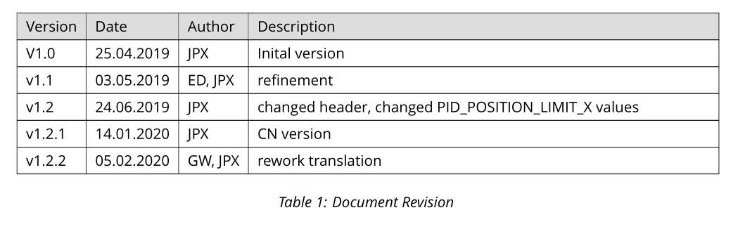
9 Revision History
mark