
Stepper motors are popular in computer- and microcontroller-based position control applications, such as robotics, industrial automation, CNC machines, 3D printers, and camera control. Because of their simple internal structure and limited number of connecting wires, stepper motors appear deceptively simple. Online, one often sees—and there are even many tutorials on—how to control stepper motors using legacy L293D driver ICs and Arduino, but for serious applications, everything depends on the quality and features of the motor driver.
Common Stepper Motor Driver Types
Pluggable Driver Modules
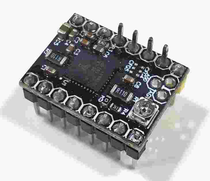
If you work on hobby projects involving stepper motors, or are building a 3D printer, you may be familiar with pluggable driver modules. They consist of a small PCB with a stepper motor driver IC and pin header connectors, allowing the module to be plugged into a larger circuit board.
There are many types of pluggable driver modules, with driver ICs available from multiple semiconductor manufacturers. Some high-end ones are the so-called SilentStepSticks built around Trinamic stepper driver ICs, among which the TMC2100 and TMC2130 are the most popular.
These SilentStepSticks are ideal for 3D printing applications, especially during long print jobs. With less advanced drivers, stepper motor noise can quickly become annoying. SilentStepSticks not only allow the printer to run quietly but also help achieve better, smoother, and more consistent print results.
In addition to the standard Enable, Step, and Dir signals, drivers based on the TMC2130 and TMC5160 also have an SPI interface, which can be used to adjust and configure multiple driver parameters. Modern 3D printing software such as Marlin supports these drivers and can even automatically adjust the motor driver via the SPI interface during printing to achieve optimal results.
Although pluggable driver modules are very small and easy to replace, they also have many disadvantages. Because of their very small size, most driver ICs use integrated MOSFETs and are prone to overheating even without a heatsink on top. This is mainly a problem in more demanding applications such as CNC.
In addition, pluggable driver modules do not provide electrical isolation between the motor power supply and control signals, making them unsuitable for complex motion control systems.
Industrial Stepper Motor Drivers
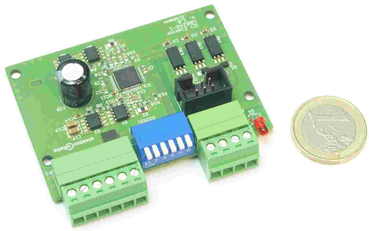
Industrial drivers are typically used in a wide range of applications and are mostly housed in enclosures with terminal boxes for connecting the power supply, motor wires, and control signals. Often, the enclosure also serves as a heatsink for the internal electronics. Some driver enclosures are even suitable for direct mounting on the back of a stepper motor. DIP switches are commonly used to configure key driver parameters such as microstep and motor current. More advanced drivers also provide a serial port or USB interface for configuring and tuning motor parameters.
Industrial drivers tend to have optocoupler inputs, providing electrical isolation for control signals (Enable, Step, and Dir signals). Some drivers use ModBus (or even CAN bus) to control motor position, speed, and direction.
In summary, two types of drivers are available: open-loop and closed-loop. The latter uses a rotary encoder to feed back the motor shaft position to the driver. If the motor loses steps under certain load conditions, it can provide higher accuracy and compensation. If multiple stepper motors need to be driven, multi-axis motor drivers are also an option.
Trinamic TMC2160 Motor Driver IC
Our "Wolverine" CNC gantry robot (published in Parts 1 and 2) is based on Eding CNC's CNC310 control board. Since the CNC310 board requires external stepper motor drivers, we considered using drivers based on Trinamic ICs. This would allow the CNC gantry robot to run quietly, which is especially important when using the machine as a pick-and-place machine for SMT components.
Initially, we performed some quick tests using TMC2100 and TMC2130 SilentStepSticks, but these could not complete the task and would quickly overheat. Instead, we looked at the brand-new TMC2160, which uses external MOSFETs and is designed for higher-power applications (Figure 1).
TMC2160 adapter boards are available, but unfortunately the motor driver parameters can only be configured via SPI, which the CNC310 board does not support. In addition, there is no electrical isolation between the control signals and the motor power supply.
Finally, we designed our own TMC2160-based driver, in which the IC operates in standalone mode and has optocoupler inputs for control signals. This allows the motor driver parameters to be set using DIP switches.
Most modern stepper motor drivers (such as the TMC2160) are so-called chopper drivers, which can quickly switch a relatively high voltage on and off (typically eight times the rated motor voltage for optimal results). This technique allows the average current of each phase to be controlled. Most chopper drivers use a chopping frequency in the 20–50 kHz range. Because the chopping frequency is above the audible range, the noise level remains low. At a constant fixed chopping frequency, the average output current is controlled by changing the pulse width of the output pulses; this technique is called pulse-width modulation (PWM).
In addition to the classic constant off-time chopper, the TMC2160 has two sophisticated chopper modes, SpreadCycle and StealthChop2, which ensure noiseless operation with maximum efficiency and optimal motor torque.
StealthChop2 is based on the principle of a voltage chopper. It especially ensures that the motor remains quiet at standstill and at slow speeds, but ball bearings can produce noise. Unlike other voltage-mode choppers, stealthChop2 does not require any configuration. During the first motion after power-up, it automatically learns the optimal settings and further optimizes them in subsequent motions. The initial homing sequence is sufficient for learning. StealthChop2 achieves high motor dynamics by reacting immediately to changes in motor speed.
SpreadCycle is an advanced cycle-by-cycle chopper mode. It provides smooth operation and good resonance damping over a wide range of speeds and loads. The SpreadCycle chopper scheme automatically integrates and adjusts the fast decay period to ensure smooth zero-crossing performance and achieve high dynamics and maximum peak speed with low vibration.
Other advances in the TMC2160 include MicroPlyer step interpolation, resonance damping for mid-frequency resonance, DcStep load-dependent speed control, StallGuard high-precision sensorless motor load detection, and CoolStep current control, which can save up to 75% energy. For more information, please refer to the TMC2160 product page and datasheet.
The circuit diagram is shown below:
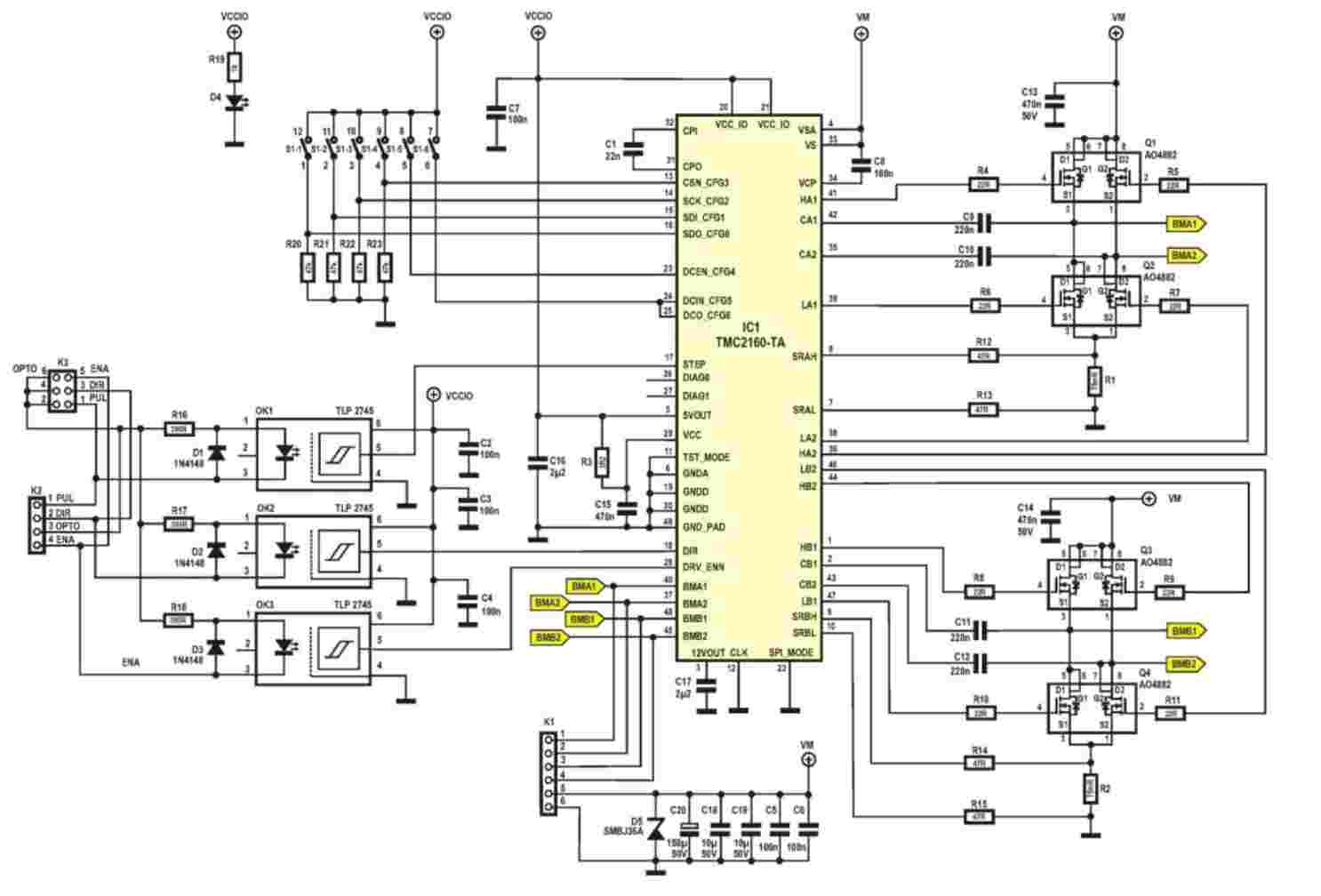
The screenshot may not be clear enough after zooming in; you are welcome to contact us to obtain the original image.
sales@chiplinkstech.com, sales08@chiplinkstech.com,
https://www.chiplinks.cn/,