
Wearable devices, miniature optical modules, insulin pumps, and small print/scan mechanisms—almost all of these products have a stepper motor responsible for precise positioning of some mechanism. For a long time, the solution for driving this motor has stayed on the old path of “one driver chip + one MCU + a pile of peripherals.” The MCU has to calculate acceleration and deceleration itself, sense resistors must be placed on the board, and with lithium-battery power you also have to worry about standby current all the time.
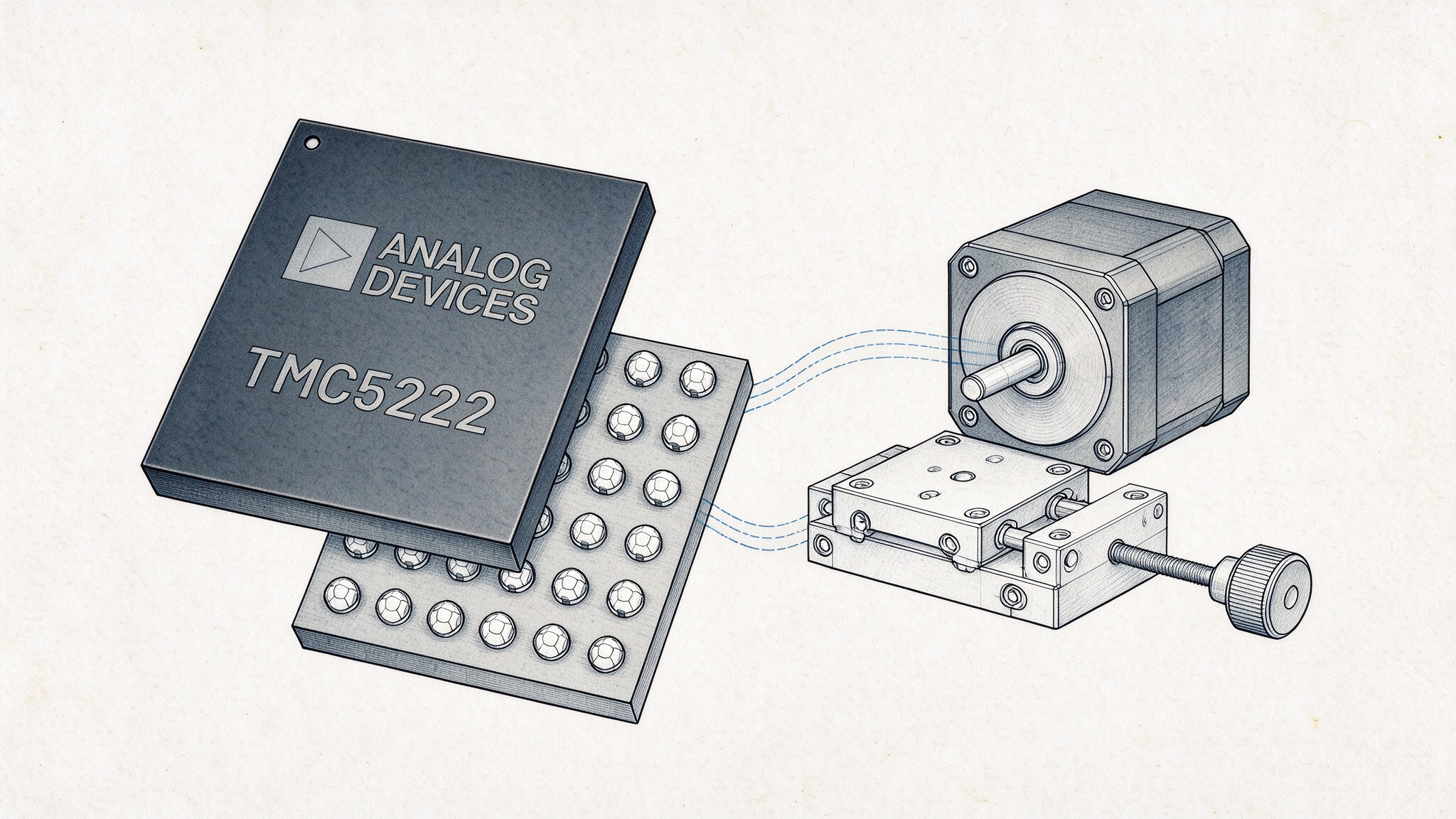
TMC5222 packs all of this into a single 2.49 × 2.3 mm chip.
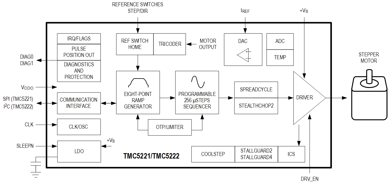
It does two things at once. One is power driving: the chip integrates two full-bridge power stages, and the two-phase windings connect directly to the outputs, so no external drive transistors or power amplifier are needed. Power it up and send a command, and the motor turns. The supply range is 2.1 V to 16 V with 1.4 A RMS continuous current (2 A sine peak), covering motors from direct lithium-battery drive up to small 12 V systems; it also has built-in lossless current sensing (ICS), which eliminates external sense resistors. The other is motion control: trajectory generation no longer relies on the MCU. The chip calculates the speed profile needed to move the motor from point A to point B; the MCU only needs to send the target position.
Functional block diagram
The chip’s built-in ramp generator is responsible for “calculating” this profile. It splits the entire movement into three acceleration segments and three deceleration segments; two speed thresholds automatically switch between different acceleration/deceleration settings for the low-, medium-, and high-speed segments, forming an eight-point speed profile. The reason for such fine segmentation is that a stepper motor’s pull-out torque decreases as speed rises: at low speed there is surplus torque, so it accelerates hard; at high speed torque is insufficient, so it decelerates earlier. The acceleration/deceleration profile hugs the motor’s torque curve, so it never exceeds the torque available at each speed and loses steps, while using the margin fully to run faster. If the load suddenly becomes heavier and the motor is close to losing step, the chip also has DcStep, which automatically reduces the speed.
More practically, it supports real-time target-position updates during motion—whenever the MCU sends a new target, the chip continues planning from the current speed and position without stopping midway to wait for commands. If the device is still moving farther away and you suddenly change the target to a closer one, it decelerates directly from the current speed and recalculates the profile; if the new target is so close that one deceleration cannot reach it, it will overshoot and then reverse a short segment to stop stably. Conversely, if the target is changed farther away, it continues accelerating toward it. This feature makes joystick-style continuous control very clean—for surveillance gimbals, optical lens groups, and similar equipment, the operator keeps moving and the target position keeps changing; the ramp generator handles each transition itself, and the MCU never has to intervene in acceleration/deceleration.
After the motor stops, power consumption and position reliability are the two most critical considerations.
Traditional solutions generally take one of two paths here: one is to keep the power on continuously to maintain torque—torque is available, but the battery cannot sustain it; the other is to cut power to save energy, but if an external force nudges the rotor, steps are lost, and the next startup requires re-homing. TMC5222's TriCoder takes a third path—with no power applied to the windings, it uses back EMF to 'see' whether the rotor has been turned by an external force.
After stopping, two states are selectable. In freewheeling mode, the windings are open-circuited, the driver stage consumes essentially no power, back EMF appears directly across the coil terminals, and TriCoder has the highest detection sensitivity; in passive braking mode, the low-side power transistors are turned on to short-circuit the windings, the rotor is damped by eddy currents and feels 'heavier' to turn, at the cost that the back EMF must first be converted into coil current and then into voltage via the low-side MOSFETs' RDS(on), reducing sensitivity. For the lowest power consumption and highest detection sensitivity, choose freewheeling; when additional mechanical damping is needed (e.g., vibration resistance at standstill), use passive braking.
Once an external force turns the rotor, the back EMF in the windings is captured by the chip, so it knows the rotor has moved and can calculate how many full steps it has turned. This position information is accumulated in the BEMF counter and compared with the ramp generator's internal position count for difference compensation. The result: if the device has been jostled all the way in a bag, after restarting, the chip knows how much it was moved by external force during power-off, so forced re-homing is not required every time. It can even use the motor in reverse as an input device—manually turning the mechanism, the chip recognizes the action, for teaching positions or user interaction.
For battery-powered devices, power consumption is squeezed out layer by layer. The chip can use StallGuard2/4 to measure the motor's actual load in real time and CoolStep to dynamically adjust the current—reducing current under light load and saving up to about 75% of power consumption. Standby while stopped also has distinctions: in deep sleep mode, all internal power supplies are turned off and current drops to the minimum, at the cost that all registers are reset after wake-up and must be reconfigured; in low-power quiet mode, chip power consumption is reduced to 23 µA (50 µA when TriCoder remains enabled), register contents are retained, the communication interface remains active, and TriCoder keeps watching the position and can respond as soon as a command is received.
Precision and quietness are ensured by the chip using 256 microstepping together with the StealthChop2 chopper algorithm. 256 microstepping divides each full step into 256 levels, and even if the MCU provides only a low-resolution step signal, the chip can use MicroPlyer interpolation to achieve the smoothness of full 256 microsteps, greatly reducing the pulse burden on the host controller. Combined with quiet chopping, the motor has almost no audible noise at low speed and standstill, which is basically a hard requirement in optical and medical equipment. When higher dynamic response is needed, SpreadCycle chopper mode can also be switched to. On the load detection side, StallGuard2 and StallGuard4 provide sensorless solutions: they can provide stall protection and also eliminate limit switches for sensorless homing. The two detection schemes belong to different chopper modes: StallGuard4 with StealthChop2, and StallGuard2 with SpreadCycle.
In development and production, TMC5222 also takes on a lot itself. Motion parameters and current settings can be permanently stored in the chip's one-time programmable (OTP) memory, automatically loaded at power-up, so the MCU in a multi-axis system does not need to resend the configuration at every startup. These parameters can also be bit-locked to prevent accidental modification during operation. Before mass production, OTP prototype validation can be performed first—running the configuration sequence in simulation inside the chip to confirm correct behavior before actual programming. The chip's own safety protection is also complete: overcurrent, overtemperature, undervoltage, and short circuit all have corresponding responses, and there is also a hardware emergency stop path—the DRV_EN pin directly turns off the output stage, bypassing all digital logic and software, providing a backstop for the mechanical safety of critical equipment.
In the same family, there is also a pin-compatible device, TMC5221; the two have identical internal hardware modules and algorithmic capabilities, with differences only in the communication interface:
- The TMC5222 uses an I²C interface, making it more suitable for multi-node deployment; a single bus can host multiple point-to-point positioning mechanisms, fitting the development needs of portable and wearable devices;
- The TMC5221 features an SPI interface, supports 40-bit data frames and daisy-chain connection, and offers higher communication throughput, making it more suitable for instrumentation equipment that requires high-frequency reading of load and real-time stall status.
The interface levels of both chips are lowered to 1.1 V to 2 V, allowing direct connection to low-voltage GPIO on mobile platforms without additional level shifting.
Thanks to pin compatibility, after the PCB design is finalized, switching between the two bus options can be completed simply by changing BOM components. Both chips support two operating modes at the same time: the on-chip hardware motion engine can be enabled, with the MCU issuing a target position and the chip autonomously performing acceleration/deceleration point-to-point positioning moves; alternatively, the internal motion controller can be disabled, external STEP/DIR pulses can be received, and the MCU can take full responsibility for trajectory planning, with the chip operating solely as a pure driver device.
This set of features provides greater flexibility for prototype validation and deriving multiple product versions. In the early project phase, the integrated drive-control mode can be used to quickly complete prototype validation; later, if the bus interface does not match and parts need to be changed, replacing the TMC5222 with the TMC5221 (or vice versa) is sufficient, with no PCB redesign required, greatly reducing the time cost of hardware changes. As for the two modes—integrated drive-control and pure drive—the same chip can switch back and forth simply by changing its configuration.
For battery-powered, PCB space-constrained miniature point-to-point positioning devices that need a streamlined BOM and reduced motion-algorithm burden on the main controller, the TMC5222 is a mature integrated solution. The pin-compatible TMC5221 in the same series also leaves ample room for product trade-offs between I²C and SPI.
For more information about the TMC5222 or to request samples, please contact: sales@chiplinkstech.com; Engineer Chen, 13924675549.
Attached parameter table:
| Parameter/Function | Specification |
| Supply Voltage | 2.1V~16V |
| Continuous Coil Current | 1.4 A RMS (2 A sinusoidal peak) |
| Output Stage On-Resistance RDS(ON) | 0.17Ω (high-side + low-side, typical) |
| Microstep resolution | Up to 256 microsteps per full step (MicroPlyer interpolation) |
| Package size | 30-pin WLCSP, 2.3 mm × 2.49 mm |
| Operating temperature | -40℃~125℃ |
| Standby power consumption | Low-power quiet mode: 23 µA |
| Current Sensing | Lossless Current Sensing (ICS) |
| Motion Control | 32-bit Motion Controller + 8-Point Ramp Generator |
| Chopper Mode | StealthChop2 (Silent) / SpreadCycle (High Dynamic) |
| Load Detection | StallGuard2 + StallGuard4 |
| Adaptive Energy Saving | CoolStep, up to approx. 75% savings |
| Stall prevention to avoid step loss | DcStep (automatic speed reduction on overload) |
| Standstill position detection | TriCoder (back-EMF sensorless standstill step-loss detection) |
| Communication interface | TMC5222:I²C;TMC5221:SPI |
| Safety protection | Overcurrent/overtemperature/undervoltage, adaptive short-circuit protection, DRV_EN hardware emergency stop |

Sample request attached

WeChat Official Account