
In complex embedded systems such as industrial control, communications infrastructure, and servers, the I²C bus has become the preferred solution for peripheral management and low-speed communication due to its simple architecture and low wiring cost. However, as the number of system peripherals increases and voltage domains diverge, the I²C bus has long faced three typical engineering constraints: address conflicts caused by fixed addresses of same-model slave devices, inability of devices in different voltage domains to communicate directly, and cumbersome management of multi-channel peripheral interrupt signals.
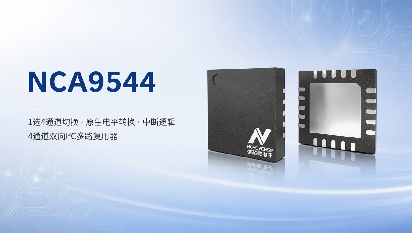
For such long-standing industry design needs, the NCA9544 4-channel bidirectional I²C multiplexer integrates channel switching, level translation, and interrupt management, providing a highly integrated, highly reliable domestic solution for I²C bus expansion.
1. 1:4 Bidirectional Switching Solves Address Conflicts
NCA9544 is a 1:4 bidirectional multiplexer configured by the I²C bus, in a QFN20 (5×5) package. Functionally it is divided into five groups: one upstream pair SCL/SDA connected to the host controller; four downstream pairs SC0/SD0 to SC3/SD3, each connected to a group of peripherals; four interrupt inputs /INT0–/INT3 and one interrupt output /INT; three address pins A0/A1/A2; plus VCC and GND. To the host controller, it is an ordinary I²C slave device—occupying one slave address and configured by writing registers.
The upstream master-side bus can be flexibly switched to any one of four downstream channels via the on-chip 8-bit control register; only a single channel is conducted at a time, fundamentally solving bus attachment conflicts among multiple same-address slave devices (such as multiple digital temperature sensors).
To ensure communication stability, channel switching takes effect only after the I²C Stop condition occurs: at this point all four pairs of downstream lines are at high level, so at the instant of connection the slave side will not misinterpret them as Start or Stop conditions. The device also includes a power-on reset (POR) circuit; after V_CC rises above the reset threshold, the registers are automatically cleared and all four channels remain disconnected, so there is no glitch during power-up and same-address downstream devices will not be attached to the upstream bus together during host initialization.
Branching also solves another problem. I²C has a 400pF upper limit on the total parasitic capacitance of a single bus SDA/SCL; with many peripherals and long traces, it easily exceeds this limit, manifesting as slower edges and communication errors. After splitting one bus into four, the load is distributed across branches, and only one branch is connected upstream at any time; all peripherals are no longer stacked on one line, so the same 400pF budget can support more nodes.
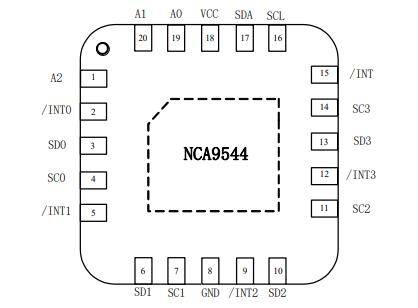
Pin View
Native Level Translation for Multi-Voltage-Domain Systems
In mixed-voltage systems, I²C interoperation among 1.8V, 2.5V, 3.3V, and 5V devices often requires additional level-translation chips, increasing BOM cost and routing complexity. NCA9544, through its transmission-gate voltage-clamping design, natively supports bidirectional translation across multiple voltage domains.
The maximum conduction voltage of the device's transmission gates is clamped by the VCC supply, and with independent external pull-up resistors on each channel, bidirectional communication between buses at different voltages can be achieved. In design, it is only necessary to keep the highest level that a channel can pass no higher than the lowest bus voltage in the system; each downstream channel is then pulled to its target level by its own pull-up resistor, enabling cross-voltage-domain interoperation among 1.8V/2.5V/3.3V and 5V devices.
NCA9544 supports a wide supply range of 1.65V to 5.5V, and all IO ports are rated for 5.5V, so even when upstream/downstream bus voltages are higher than the chip supply, it can operate safely and stably, fully meeting the design needs of various mixed-voltage systems.
Integrated Interrupt Logic for Lower System Management Overhead
Peripheral alarms are a common requirement on the I²C bus. When a temperature sensor crosses a threshold, it pulls its alert pin low; the host needs to know this. However, four sensors mean four alert lines, and the host's GPIOs and external interrupt sources may not be sufficient. As a fallback to polling, the host would have to switch through all four channels at fixed intervals and read the status registers one by one; the more channels there are, the slower each cycle becomes.
The NCA9544 integrates a complete interrupt logic unit: it provides four active-low interrupt inputs, /INT0 through /INT3, each with an independent pin connected directly to the alarm output of the corresponding downstream channel device; the four signals are ANDed on-chip and sent to the host controller via one active-low, open-drain /INT—if any input is pulled low, /INT is pulled low accordingly. These four inputs use paths independent of SCL/SDA and do not pass through the internal switches.
Therefore, interrupt detection and channel selection are independent of each other. Even if a branch is not selected and its switch is completely open, a device connected to it can pull its alarm line low; the chip still captures it, and /INT is still pulled low. After the host controller responds to the interrupt, it only needs to read the device control register over I²C to quickly identify the channel to which the interrupt belongs, then switch to the corresponding channel to handle the interrupt source, eliminating the overhead of polling all channels and greatly improving system response efficiency.
If interrupt functionality is not required, the interrupt input pins can be repurposed as general-purpose input ports; unused interrupt pins must be connected to VCC to ensure stable device operation.
4. Flexible Expansion + High-Reliability Design, Suited to Harsh Environments
Multi-level cascading expansion: The device is equipped with three hardware address pins, A0/A1/A2. By connecting them to GND or VCC, 8 different slave addresses can be configured. Up to 8 NCA9544 devices can be connected in parallel on a single I²C bus, expanding to 32 downstream I²C channels, easily supporting large-scale peripheral arrays.
Low-loss high-speed communication: The transmission gate's on-resistance is 20 Ω maximum and 14 Ω typical at VCC = 4.5 V, resulting in low signal attenuation. It supports Fast-mode communication rates up to 400 kHz and is compatible with I²C and SMBus, meeting the communication requirements of most low-speed peripherals.
Industrial-grade reliability: The device's latch-up performance exceeds 100 mA (compliant with JESD78), and ESD protection reaches 2000 V human body model (HBM) and 1000 V charged device model (CDM); maximum operating current is 10 μA and standby current is 5 μA (VCC = 5.5 V, no load), so it places no burden even when continuously powered on battery-powered boards; operating temperature covers -40°C to 105°C, and it meets RoHS and REACH environmental requirements.
5. Diverse Application Scenarios Covering Multi-Domain Needs
With comprehensive functions and reliable performance, the NCA9544 can be widely used in various I²C bus expansion scenarios:
- Servers and storage devices: On the BMC out-of-band management bus, temperature sensors are typically multiple devices of the same model and address; the switch assigns each type of device to a branch, and the BMC enables the required branch on demand, so one upstream bus can cover the monitoring points of the entire board;
- Telecom switching and routing equipment: Service boards in a chassis each have their own management bus. When they converge to the main controller, they must both be merged and matched to voltage domains—it is common for 3.3 V and 5 V devices from new and old boards to be mixed on one line. Here the multiplexer is both a convergence point and a conversion point;
- Factory automation systems: Distributed I/O and sensor nodes are distributed along field wiring. When dozens of slave nodes hang on one main bus, they are divided into branches by area. Reading and troubleshooting are performed branch by branch, without traversing all nodes each time;
- Multi-sensor monitoring arrays: Multiple temperature, magnetic, and optical sensors of the same model are arranged side by side and read one by one through channel switching. The main controller side maintains only one slave address.
As an important member of the interface product line of its manufacturer, NCA9544 streamlines the BOM and design cycle of I²C expansion solutions with a highly integrated design, while providing a high-quality domestically sourced bus expansion option for embedded system designs in various fields through industrial-grade reliability and flexible adaptability.
For more information about NCA9544 or to request samples, please contact: sales@chiplinkstech.com; Mr. Chen, 13924675549.
Appendix: Parameter Table
| Category | Item | Parameter |
| Channels and Addressing | Number of Channels | 1-of-4, bidirectional |
| Slave address | 0x70–0x77 (A0/A1/A2 hardware configuration) | |
| Cascade Scale | 8 devices in parallel, 32 downstream channels | |
| Power Supply and Levels | Supply Range | 1.65 V ~ 5.5 V |
| I/O Withstand Voltage | 5.5 V | |
| Level Shifting | 1.8 V / 2.5 V / 3.3 V / 5 V bus interconnection | |
| Switching Performance | On-resistance | 14 Ω typ,20 Ω max(VCC=4.5 V) |
| Communication rate | 0 ~ 400 kHz, compatible with I²C and SMBus | |
| Bus capacitance | ≤ 400 pF per line | |
| Switching timing | Effective after the stop bit | |
| Interrupt | Input | 4 channels, active low |
| Output | 1 channel, open-drain, active low | |
| Status bit | Upper 4 bits of the control register, read-only | |
| Power Consumption and Reliability | Operating / Standby Current | 10 μA max(VCC= 5.5 V, no load) / 5 μA max |
| ESD | ±2 kV HBM,±1 kV CDM | |
| Latch | > 100 mA(JESD 78) | |
| Operating temperature | −40 ℃ ~ 105 ℃ | |
| Package | QFN20,5.0 × 5.0 mm |