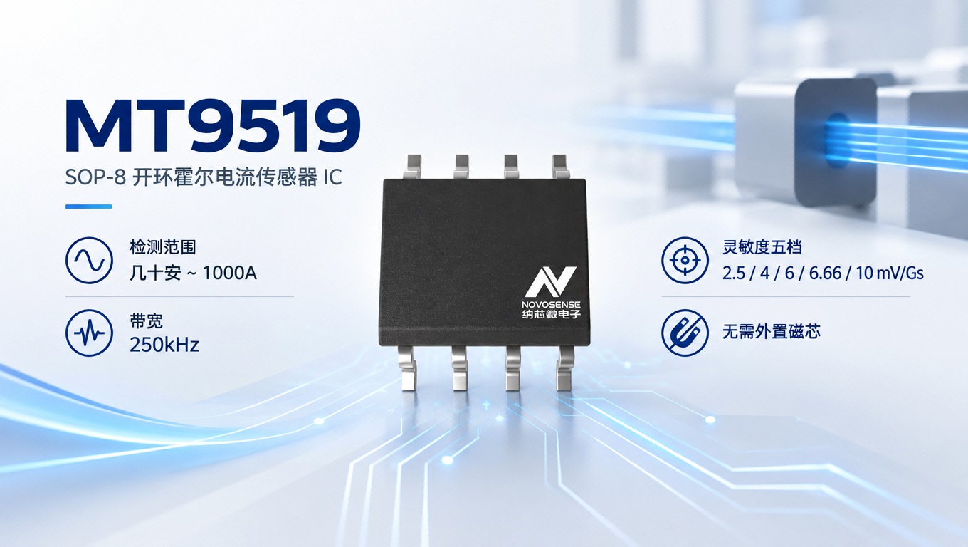
SOP-8, an eight-pin package just a few millimeters square, normally houses only op amps, logic gates, low-power supplies, and the like. Saying it can measure 1000A usually gets an immediate “impossible”—whichever pin 1000A enters, that pin would burn.
There are generally two common ways to measure high current. One is a shunt resistor: pass the current through a milliohm-level resistor and measure the voltage drop across it, but at the 1000A level, even a resistor of only 0.1mΩ dissipates 100W, bringing heat dissipation, temperature drift, and common-mode interference together. The other is a magnetic sensor: measure the magnetic field generated by the current. The traditional approach requires adding a magnetic core or flux concentrator ring to concentrate the field; the core is bulky, can saturate, has hysteresis, and installation is also direction-sensitive.
MT9519 is an open-loop Hall current sensor, and it takes a third approach: no series resistor and no external magnetic core. Looking at its eight pins laid out, only three are actually connected: pin 5 VCC, supplied from 4.5V to 5.5V; pin 3 GND; pin 6 VOUT, analog voltage output. The remaining pins 1, 2, 4, 7, and 8 are NC. It has no measured-current input pin and no current output pin; instead, the copper bar or busbar itself serves as the primary current path, and the chip is mounted beside it to read the magnetic field. The busbar carries the current and the chip reads the magnetic field—the two functions are separate—so the SOP-8 package can also be used for system-level current sensing up to 1000A. The primary current does not pass through the chip, so there is no primary conduction loss.
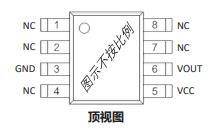
Pinout view
However, conventional Hall elements are usually sensitive only to magnetic fields perpendicular to the chip surface. When the chip is mounted flat against the busbar, the magnetic field direction does not align with the sensitive direction of an ordinary Hall element. MT9519 uses HMD technology and integrates two magnetic flux concentrators inside the chip to guide and redirect the magnetic field, making the device as a whole sensitive to magnetic flux density parallel to the chip surface. This allows the chip to be mounted flat against the busbar, without standing it upright or inserting an external magnetic core or flux concentrator ring between the busbar and the chip.
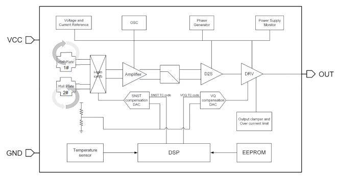
Functional block diagram
The MT9519 series has five factory sensitivity settings: 2.5, 4, 6, 6.66, and 10mV/Gs. Lower sensitivity means a larger range, and the series covers tens of amps to 1000A. How much a specific board can measure depends on the busbar geometry, chip mounting position, and which setting is selected.
For speed, the bandwidth is 250kHz, step response is 2.2μs (typical), and propagation delay is 1μs; the output keeps up with fast current changes. For accuracy, typical accuracy at 25°C is ±1.0% and linearity is ±0.5%; over the full operating temperature range, sensitivity drift is ±1.5%. The zero-point output is 0.5VCC with ±10mV error; it is a ratiometric output, and the output varies proportionally with the supply voltage.
The supply is 5V, with typical consumption of 15mA. The output includes clamping and overcurrent limiting: output current is limited to ±55mA, overcurrent detection is 10μs, and release is 1ms. Operating temperature is -40°C to 150°C, and the junction temperature limit is 165°C. Sensitivity, zero-field output, and temperature compensation are programmable, with 200 programming cycles; ESD is per AEC-Q100, HBM Class 3B, CDM C3 rating.
| Supply/Power Consumption | 4.5V~5.5V, typical 15mA |
| Bandwidth/Response | 250kHz, step response 2.2μs (typical) |
| Accuracy/Linearity | ±1.0%(25°C)/±0.5%(25°C) |
| Sensitivity drift over full temperature range | ±1.5% |
| Sensitivity setting | 2.5 / 4 / 6 / 6.66 / 10 mV/Gs |
| Output | Ratiometric output, 0.5VCC at zero field (±10mV), with clamping and ±55mA current limiting |
| Operating temperature | -40℃~150°C |
| Package | SOP-8 |
In summary, the MT9519 is a high-reliability, high-performance current sensor with no external magnetic core/flux concentrator. It targets automotive traction motor inverters, photovoltaic inverters, battery management, uninterruptible power supplies, and overcurrent protection. These applications share common requirements: high current, isolation, tight board space, and no desire to insert a large series resistor in the loop.
However, there are a few points to note.
First, it measures the magnetic field of the busbar, and its range and accuracy are strongly related to the busbar shape and the chip mounting position. If the busbar is changed or the spacing is adjusted, the sensitivity must be recalibrated. It is not a device that can read 1000A simply by being soldered on—the structure is part of the design.
Second, it is not connected in series in the current loop, and there is no electrical connection between the chip and the busbar; however, the isolation capability depends on the distances and materials of the busbar, chip, and surrounding structure—it is not an isolation rating provided by the chip alone. For high-voltage systems, creepage distance and insulation must be calculated based on the complete system structure.
Third, it is an open-loop solution, with a typical accuracy of ±1.0% at 25°C. If the system requires higher accuracy or closed-loop operation, that is a problem for another type of product to solve.
The SOP-8 can measure 1000A not because the chip carries the current, but because of a different approach: let the busbar carry the current and let the chip read the magnetic field. The issues of primary-side conduction loss, magnetic core volume, and mounting orientation are thereby addressed with a different solution.
For more information about MT9519 or to request samples, please contact: sales@chiplinkstech.com; Mr. Chen, 13924675549.
Sample request attached:

WeChat Official Account