
Stepper motor driver chips have become increasingly complex in recent years. High-end chips are no longer satisfied with power driving; they have integrated motion control cores as well, receiving target position commands over SPI and performing acceleration/deceleration planning internally. Along with this intelligence, control has been taken away from the main MCU—you can no longer control the motor with familiar timer interrupts and GPIO toggling; instead, you must dig through complex manuals and learn vendor-defined instruction sets and state machines. If a single configuration word is written incorrectly, the motor will not move at all, yet the only debugging tool is a logic analyzer. Various fancy algorithms become a black box when the load changes, and troubleshooting relies entirely on blind trial and error.
But for some applications, all that is needed is a quiet, reliable, cost-controllable drive solution—the MCU sends STEP/DIR pulses, a few GPIOs handle the control logic, and the motor simply turns without problems. In such scenarios, those complex features are not a bonus but a burden. The MS35776 series is designed for this type of requirement: no SPI registers, no complex algorithms, works as soon as powered on, letting the driver return to being a driver.
1. Parameter Overview: Standard and Practical
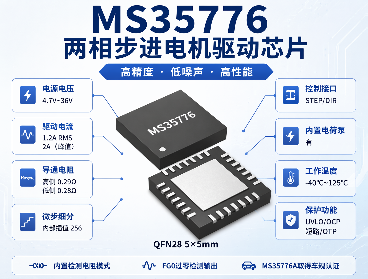
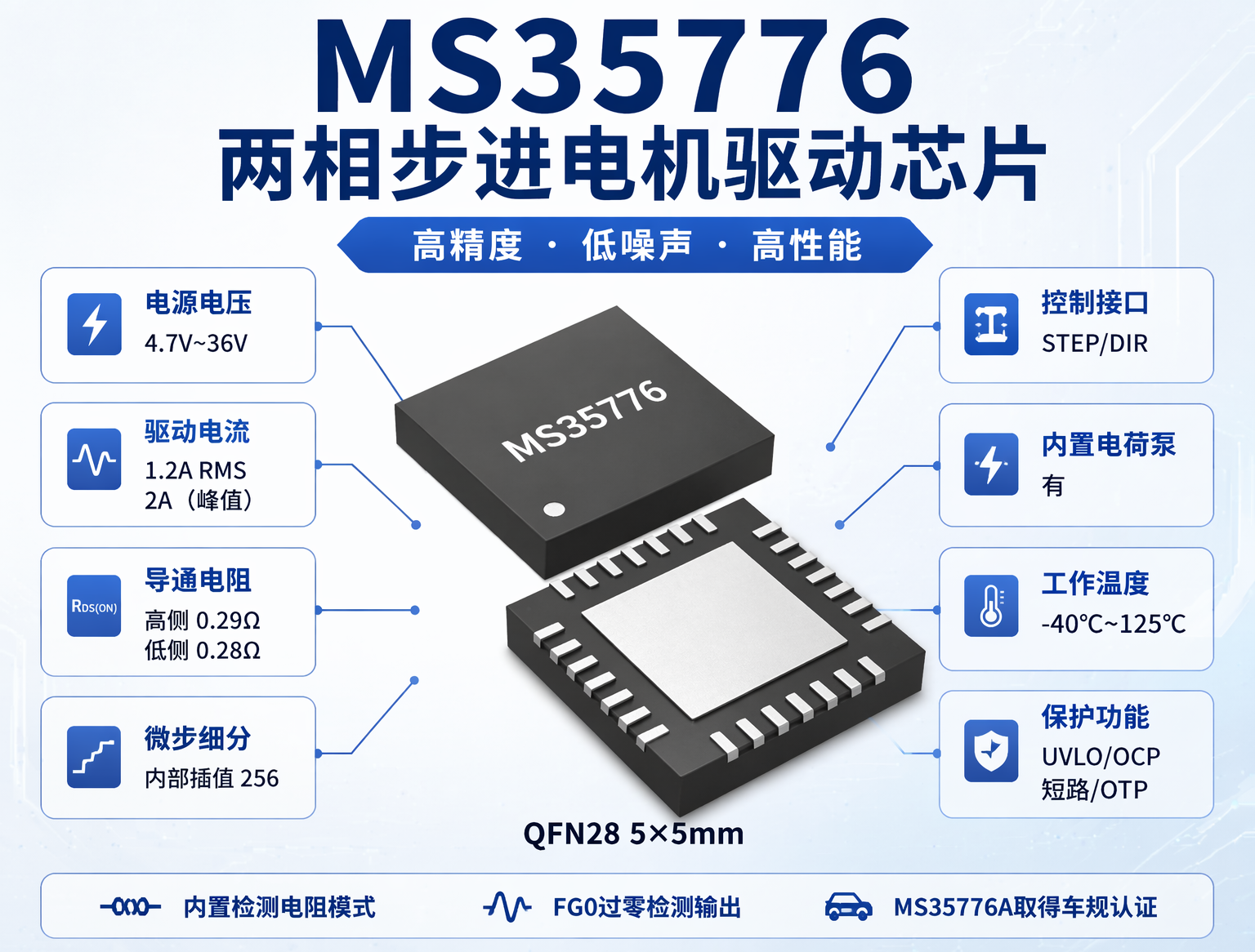
The MS35776 is a two-phase stepper motor driver chip in a QFN28 package with integrated power MOSFETs, a 2 A peak output current, and a 1.2 A continuous average operating current. The QFN28 package has a large thermal pad on the bottom, occupies a 5×5 mm board area, and is 0.75 mm high; its double-sided attachability allows it to fit into space-constrained structures. The operating ambient temperature is -40°C to 125°C, and the maximum junction temperature is 150°C.
| Supply Voltage | 4.7V~36V |
| Drive Current | 1.2 A RMS, 2 A (peak) |
| On-resistance | High-side 0.29 Ω, low-side 0.28 Ω |
| Microstep resolution | 256 internal interpolation |
| Control interface | STEP/DIR |
| Integrated charge pump | Yes |
| Operating temperature | -40℃~125℃ |
| Protection features | UVLO/OCP/Short Circuit/OTP |
| Package | QFN28 5×5mm |
On these parameters, it is not much different from the dozen or so chips in the same class on the market. Peak current, supply voltage, on-resistance, and microstep resolution—this segment has been highly competitive for more than ten years, and all the comparable figures have been matched across vendors. The MS35776 is just an “ordinary” two-phase driver: simple and practical, requiring no complex external circuitry, with low procurement cost. In addition, it has three things that most chips in the same class do not have.

Pin package view
II. Three Hassle-Free Design Features
1. Integrated sense resistor mode
Stepper motor drivers usually require an external sense resistor in series with each of the two-phase outputs, with resistance between 100 and 200 mΩ. The SENA and SENB pins of the MS35776 can be connected directly to ground; the chip automatically switches to the integrated sensing path, eliminating the external sense resistors and their associated issues. There are three benefits.
- ① Batch-to-batch consistency. The accuracy of external milliohm-level resistors fluctuates from batch to batch. For a nominal value of 100 mΩ, actual incoming material may range from 95 to 105 mΩ. The current reference point drifts accordingly, making it difficult to control current consistency in mass-produced products. The resistance of the integrated sensing path is formed monolithically on the silicon die, so this problem does not exist.
- ② Temperature drift. The resistance of a power resistor changes with temperature. After the motor heats up, the actual resistance of the external resistor deviates from the cold-state calibration value, and the current threshold drifts accordingly. The integrated path and the power transistors are on the same silicon die, so temperature coefficient compensation can be performed internally.
- ③ PCB area. Milliohm-level sensing requires Kelvin four-wire routing. Two channels mean four differential lines, which cannot be handled by a small resistor pad. Integrated mode also eliminates these four lines.
If there is no extreme requirement for current accuracy, integrated mode is a worry-free, area-saving choice. Of course, the MS35776 also supports external precision sense resistors; both usage methods are retained.
2. FG0 zero-crossing detection output
The FG0 pin of the MS35776 outputs the positive zero-crossing pulse signal of the A coil. Each time the motor rotates to a specific electrical angle, this pin outputs a pulse. No encoder is needed, and no SPI readback of the current waveform is needed; the pulse frequency directly corresponds to the actual motor speed.
Although an encoder tells you position, FG0 only tells you speed. But in many scenarios, knowing the speed is enough. Security PTZ cameras need to maintain a constant rotational speed, medical infusion pumps need to monitor whether the advancement speed is normal, and 3D printer extruders need to determine whether there is speed loss caused by stalling. These requirements can be solved with FG0 without adding an encoder. Among stepper driver chips in the same class, few have an independent zero-crossing output pin; the A4988/DRV8825/HR8825 do not have a separate zero-crossing output.
3. Automotive-grade version
MS35776A has obtained AEC-Q100 certification. Instrument pointers, concealed air vent actuators, LiDAR rotating mirrors, and HUD projection mirror position adjustment. These automotive scenarios require automotive-grade certification, but most of the time do not need complex SPI configuration. In the intersection of "automotive-grade + no SPI + within 2A," there are not many "simple" chips to choose from.

Internal block diagram
III. Fully hardware pin configuration, easy to get started
The MS35776 configuration method can be explained in one sentence: all functions are set by pin levels; there are no SPI registers and no initialization code.
Microstepping is controlled by two pins, MS1/MS2, supporting four settings: 1/2, 1/4, 1/8, and 1/16. Internally, there is a sine/cosine current table that can further interpolate to 256 microsteps. Each pulse on the STEP pin advances the microstep counter by one step; the chip automatically looks up the table to adjust the current ratio of the two phase coils, without requiring the MCU to output a high-frequency pulse sequence.
The operating mode is controlled by the MODE pin. When floating or high, it uses quiet mode, with current chopping adopting a low-ripple strategy, making noise controllable at low-to-medium speeds; when low, it uses fast mode, with more aggressive decay to keep up with torque at high speeds. Enable and fault clearing are managed by a single ENN pin.
The MS35776 integrates an on-chip 5V LDO (output for digital logic supply, max 25mA), a charge pump (bootstrapped from VM to VM+5V to drive the high-side NMOS), and a 12MHz internal oscillator. No external bootstrap capacitor, auxiliary power supply, or crystal oscillator is required, nor is a separate external logic power rail needed.
Current setting is achieved by inputting an analog voltage to the VREF pin; combined with the sense resistor (or built-in mode), this determines the peak current threshold. The formula is I_PEAK = (325mV/RSENSE) × (VVREF/2.5V). There is no need to write a DAC value via registers, and the current-loop response path does not pass through any digital delay.
The entire solution requires only one timer to generate STEP pulses, a few GPIOs, power-supply filter capacitors, and one charge-pump flying capacitor, and the circuit is complete. The BOM can be counted on two hands.
IV. Comprehensive Protection, Simple but Reliable
The MS35776's protection functions cover the most common fault scenarios in stepper motor drives: undervoltage, high-side/low-side overcurrent, short to ground, short to supply, overtemperature warning, and overtemperature shutdown. The FAULT pin is an open-drain output and is pulled high when a fault is detected; it can be connected to either an MCU interrupt or polling input. Pulling ENN high briefly clears the latch and the driver resumes operation.
Overtemperature protection has four threshold levels: pre-warning, 143°C, 150°C, and 157°C. It is not a one-size-fits-all overtemperature shutdown; it leaves room for a graded system response. There is about a 10°C thermal coupling difference between the power transistor and the temperature sensor. This detail is uncommon among comparable devices.
The MS35776 also has a low-power saving mode; it enters automatically when the motor is stationary in standby, without software intervention.
V. Application Scenarios
The MS35776 is suitable for low-to-medium-power stepper drive scenarios with constant load, stable speed, and no need for online adaptive parameter tuning.
- The industrial-grade version (MS35776) covers 3D printer drive systems, security PTZ gimbals, precision instrument translation stages, medical testing equipment, and desktop automation;
- The automotive-grade version (MS35776A) covers instrument pointers, HVAC vent actuators, LiDAR rotating mirrors, and HUD projection mirror adjustment.
The MS35776 is suitable for stepper motor applications within 1.4 A continuous current and below 36 V; suitable for projects sensitive to BOM cost and development cycle; and suitable for scenarios that do not require SPI and can be driven by pulses alone.
6. Conclusion
Looking back, 'advanced features' are indeed indispensable in certain high-end scenarios, but for another class of applications—vast in number, whose requirements are merely controllable cost, short development cycles, high production yield, and no inexplicable field failures—every extra transistor integrated, every register that needs configuration, and every algorithm mode that needs verification genuinely consumes R&D time and project budget. This precisely explains why 'simple' chips like the MS35776 still have a solid market: it does not do fancy things, so it is inexpensive; it has no configurable logic, so it is stable; it does not rely on esoteric algorithms, so any engineer with an oscilloscope and a multimeter can get it working.
The 'simplicity' of the MS35776 is not a feature cut; it is doing the basics that should be done well, and then removing from the BOM and code what you will not actually use. That is the 'simplicity' of the MS35776.
For more information about the MS35776 or to request samples, please contact: evan.lai@chiplinkstech.com; 18689485319, Mr. Lai.

Sample Request Attached

WeChat Official Account