
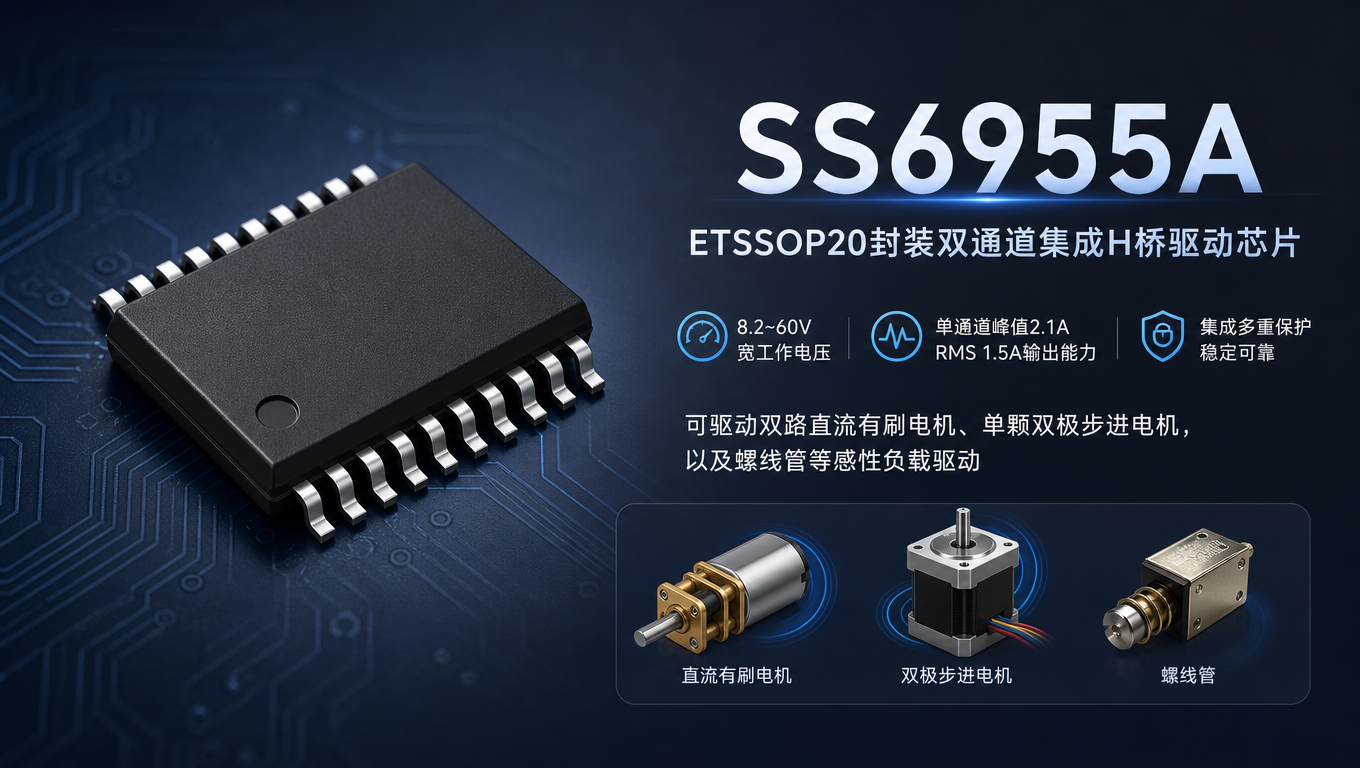
In industrial motion mechanisms, robotics, stage motion equipment, and other scenarios, 48 V high-voltage stepper and brushed DC motor drives often face pain points such as complex discrete-component peripherals, insufficient voltage-withstand margin, and missing protection. The SS6955A is an ETSSOP20-packaged dual-channel integrated H-bridge driver chip with an 8.2–60 V wide operating voltage and single-channel peak 2.1 A / RMS 1.5 A output capability. It can drive two brushed DC motors, a single bipolar stepper motor, and inductive loads such as solenoids, balancing hardware integration and system reliability.
1. Product Overview
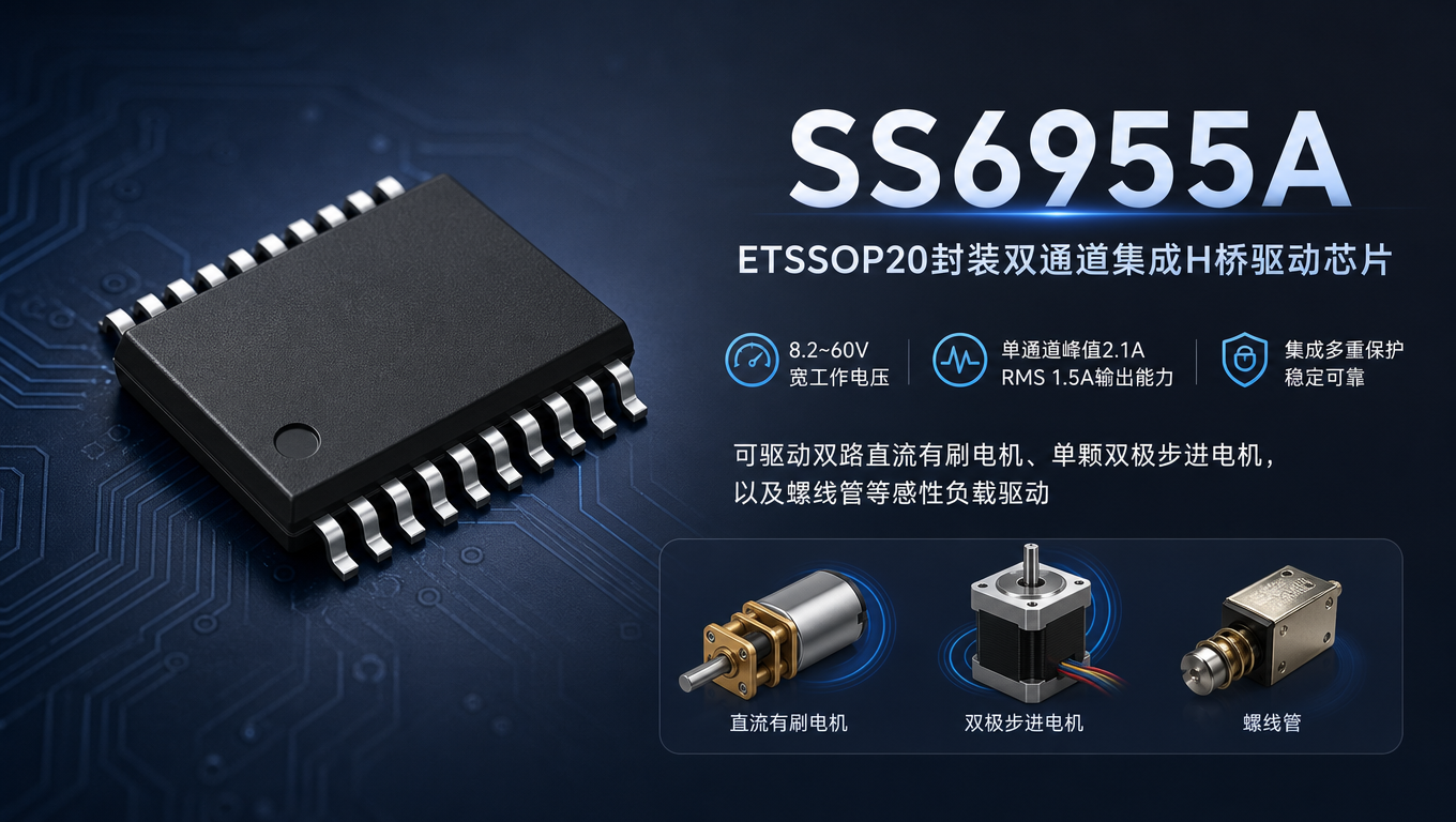
The SS6955A integrates two complete N-MOS H-bridge power units on a single chip and supports multiple output configurations: it can drive two independent brushed DC motors, or one two-phase stepper motor, and can also drive inductive loads such as solenoids. For stepper motors, high microstepping can be implemented in software, with the host controller flexibly configuring the microstepping algorithm to suit different motion-precision requirements.
The chip also integrates rectification and a programmable chopper current-limiting circuit, which can match the rated current of motors with different specifications and provide hardware-level current clamping for the motor. The default current-limiting mode is fast decay, suitable for applications requiring rapid current falloff and reduced tailing. A built-in low-power sleep mode suits energy-saving standby designs. Compared with H-bridge designs built from discrete MOSFETs, the chip eliminates external power MOSFET devices and simplifies the power-side periphery.
Key Parameters
| Operating Voltage | 8.2V~60V |
| Single H-bridge full-scale current | 2.1A |
| Single H-bridge RMS continuous current | 1.5A |
| HS + LS typical on-resistance | 600mΩ |
| Package | ETSSOP20 |
| Control interface | Compatible with PH/EN and PWM interfaces, configured by the MODE pin |
| Protection features | OCP, TSD, UVLO, nFAULT fault output |
The SS6955A supports a maximum operating voltage of 60V, fully covering mainstream 24V and 48V industrial power rails. Compared with many driver devices that have 45V/50V upper limits, it offers higher voltage margin and can more easily withstand voltage fluctuations on the power supply side and reverse load spikes in industrial environments, adapting to the power supply conditions of high-voltage motion equipment. At the same time, the 8.2V minimum operating voltage, together with UVLO undervoltage lockout, covers the undervoltage interval during power-up of high-voltage systems and avoids erroneous operation at low voltage.
Under 48V conditions (Ta=25°C), the typical total on-resistance of the chip's high-side + low-side switches is 600mΩ, and with the ETSSOP20 package this is a competitive level. The single-channel RMS continuous current is 1.5A, and the full-scale current is 2.1A. Estimated at RMS 1.5A, the single-channel conduction loss is approximately: P = I²R = 1.5² × 0.6 ≈ 1.35W; the dual-channel conduction loss is approximately 2.7W. With low on-resistance and a package with an exposed pad, 1.35W single-channel power dissipation and 2.7W dual-channel power dissipation are within the controllable range of the package's heat dissipation capability.
Under 48V and appropriate heat dissipation conditions, the chip's 1.5A RMS continuous output capability is sufficient to meet the continuous operation requirements of most 48V small stepper mechanisms, robot joints, and moving-head motors for stage lights; the 2.1A full-scale current provides transient margin during motor startup and stall conditions, preventing the startup current from being limited too early and causing the motor to lose steps or fail to start normally. Together, the two cover the complete operating conditions from steady-state operation to transient impact.
It integrates multiple protections including overcurrent, short-circuit, overtemperature, and undervoltage, and also provides an nFAULT fault signal pin. Abnormal chip states can be output to the main control unit, giving the whole machine fault-awareness capability without adding a large number of external detection circuits. For equipment such as stage lights and robots that require continuous operation and have safety requirements, the actual connection of nFAULT is directly related to the fault response capability of the whole machine. Together with the nSLEEP sleep pin, the chip's internal circuits can be turned off during standby to reduce the overall quiescent power consumption.
The hardware supports both PH/EN and PWM industry-standard control interfaces, with mode selection via the MODE pin. It can interface with most MCUs and motion controllers on the market, reducing the hardware adaptation threshold on the main control side.
II. Overview of Control Interface and Pins
The external signals of the SS6955A chip include four major categories of pins: motor drive outputs, control inputs, protection outputs, and charge pump peripherals.
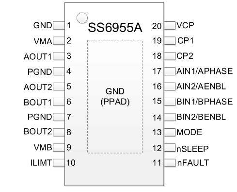
- nSLEEP: sleep control pin, used to enable/disable the chip's internal circuits and achieve low-power standby;
- nFAULT: Fault output pin. When the chip triggers overcurrent, short-circuit, undervoltage, or overtemperature protection, it outputs a fault signal so the host controller can monitor status;
- ILIMT: Programmable chopping current-limit configuration pin, used to set the upper current limit of the H-bridge output;
- MODE: Control mode selection pin, used to switch between PH/EN and PWM control interfaces;
- VCP, CP1, CP2: Charge pump-related peripheral pins, used to generate the high-side MOS transistor drive voltage and require external capacitors.
The other power pins VMA/VMB are power supply inputs for the two H-bridges, and PGND is power ground; AOUT1/AOUT2 and BOUT1/BOUT2 are the motor winding outputs of the two H-bridges.
III. Typical Application Scenarios
Industrial Motion Control Systems:48 V-powered small stepper mechanisms, valve actuators, and automated tooling equipment; the 60 V high voltage rating provides ample voltage margin to withstand power supply surges in industrial environments.
Robot actuators:Small robot joints and transmission mechanisms, driving stepper and brushed DC motors, simplifying the power driver BOM and replacing discrete MOSFET + H-bridge solutions.
Stage lighting motion mechanisms:Moving-head light motion drive, compatible with high-voltage power supply systems, drives stepper/brushed motors to perform positioning and rotation actions.
Inductive load drivers:Drives solenoid valves and solenoids; dual channels can independently control two electromagnets.
Auxiliary drive for three-phase permanent magnet synchronous motors:Can work with an external power stage/main controller for auxiliary drive of some low-power three-phase PMSMs.
4. Solution Summary
8.2 V to 60 V wide operating voltage, compatible with 24 V and 48 V industrial power supplies, with sufficient voltage margin to handle system voltage fluctuations.
Compact ETSSOP20 package with exposed pad, providing 1.5 A RMS continuous drive capability under high-voltage conditions, suitable for high-voltage motion equipment with limited board space. It also includes current limiting, protection, multiple control interfaces, hardware sleep mode, and other supporting functions to meet the equipment's routine control and status monitoring requirements.
The SS6955A is suitable for motion control systems that require high-voltage power supply and dual-channel motor drive, seek simplified drive circuits, and pursue high reliability. It can serve as a selection reference for domestic high-voltage H-bridge drivers.
For more information about the SS6955A or to request samples, please contact: sales@chiplinkstech.com; Engineer Chen, 13924675549.

Sample Request Attached

WeChat Official Account