

Disassemble the joint module of a current mainstream humanoid robot, and you will see a highly consistent mechatronic solution: “permanent-magnet synchronous frameless torque motor + high-precision harmonic reducer + servo drive + dual absolute position sensors.”
A frameless torque motor is a permanent-magnet synchronous motor with the housing, bearings, and output shaft removed. It consists of two parts, a stator and a rotor, and can be embedded directly inside a joint structure. It is widely used in key humanoid robot joints such as the shoulder, elbow, wrist, waist, hip, knee, and ankle. With high torque density and a compact structure, it works with harmonic reducers and has gradually replaced conventional housed servo motor solutions, becoming the mainstream drive solution for humanoid robot joints.

I. Why Frameless Torque Motors?
A humanoid robot has dozens of joints all over its body, from large joints that bear body weight to small joints in the dexterous end effector hands, and the requirements for motors vary greatly. However, several hard requirements happen to match the characteristics of frameless torque motors:
1. Thin space and hollow requirement.Joints are annular and flat structures, leaving limited diameter for the motor and only a thin axial thickness; they often also need a hollow bore for the transmission shaft or cables. A frameless motor removes the housing, bearings, and output shaft, leaving only the stator and rotor, so it can be embedded directly into a joint structure designed by the robot manufacturer, using the joint housing as the motor housing and the joint shaft as the rotating shaft. A housed servo motor, by contrast, is very difficult to fit in snugly.
2. Low speed, high torque, and force control.Joints need to output high torque at low speed to support the body and carry loads. Torque motors are inherently suited to low-speed, high-torque operating conditions and facilitate force control through the current loop, which exactly matches joint requirements.
3. Compact and customizable to the joint space.The frameless form allows the motor's winding and outline to be customized to the available space in the joint, rather than making the joint accommodate the dimensions of a standard motor.
II. Electrical Characteristics of Motors Under Joint Constraints
For frameless torque motors operating in joints, mainstream complete machines have operating voltages concentrated around 48 V; the voltage is kept at a relatively low level, and torque is produced by high current. Joint space is small, so even in a frameless form, motor dimensions remain constrained. At the same time, high dynamic response and force-control bandwidth are required. With these constraints combined, windings can usually only use few turns and thick wire, so the motor exhibits several electrical characteristics:
1. Low inductance
Few turns and thick wire directly result in low inductance and low resistance. The inductance of conventional servo motors is typically from a few millihenries (mH) to tens of millihenries, while the line inductance of frameless torque motors is generally within 1 mH. Take the public parameters of commercially available products as an example:
| Motor outer diameter | Line inductance | Line resistance |
| 38mm | 0.6~0.77mH | 1.29~1.68Ω |
| 68mm | 0.17~0.57mH | 0.14~0.46Ω |
| 85mm | 0.077~0.23mH | 0.065~0.23Ω |
| 130mm | 0.42~0.72mH | 0.13~0.24Ω |
(Data source: public specifications of Qianghe Motor Mosrac U series)
2. Low resistance, high current
As also shown in the table above, the line resistance of frameless torque motors is generally on the order of 0.1–2 Ω. Low resistance means higher current at the same voltage. Taking an 85 mm outer-diameter motor as an example, the line resistance is 0.065–0.23 Ω, the rated current is approximately 10 A–23.5 A, and the rated output power covers 380 W–848 W.
III. The “Three Hurdles” of Driver ICs
First hurdle: current ripple control
The low inductance of frameless torque motors means that their current slew rate is extremely high. Taking single-phase half-bridge continuous conduction mode as an example, the peak-to-peak current ripple is approximately ΔI=V×D×(1-D)×T/L, where V is the bus voltage, D is the duty cycle, and T is the PWM period. At the same duty cycle, the smaller the inductance, the larger the ripple. Under the same voltage, the same duty cycle, and the same PWM frequency, when the motor inductance drops from 1 mH to 0.2 mH, the current ripple increases by 5 times. Excessive current ripple will cause:
- Increased torque ripple, affecting the smoothness of joint motion;
- Increased motor iron loss and copper loss, reducing efficiency;
- Audible noise.
Solution direction: A higher PWM frequency can effectively reduce current ripple (doubling the frequency halves the ripple). However, a higher PWM frequency also brings the problem of increased switching loss—the driver chip needs to find a balance between frequency and efficiency.
Second challenge: current-loop bandwidth
The low inductance and low resistance of frameless torque motors result in a very small electrical time constant (τ=L/R). Taking an 85 mm motor as an example: τ=0.16 mH/0.17 Ω≈0.94 ms. In contrast, the electrical time constant of conventional servo motors is typically in the range of several milliseconds to over ten milliseconds.
Because the control period of the current loop must be much smaller than the motor's electrical time constant, typically 1/10 to 1/20 of τ, only then can the closed current loop converge stably and keep up with rapid current changes. Therefore, to precisely control this “fast variable,” the current loop of the driver chip must have sufficiently high bandwidth, and the control period is usually required to be 10–100 μs (i.e., a sampling frequency of 10 kHz–100 kHz). Excessive delay will directly cause motor jitter or overcurrent.
Third challenge: Current sensing
The two electrical characteristics of frameless torque motors compound to impose higher requirements on current-sensing accuracy and speed: low inductance makes the current change extremely fast (high di/dt), requiring fast sampling; high current results in large current amplitude and high common-mode voltage across the shunt resistor, requiring a wide sensing range, sufficient resolution, and no clipping at high currents. Combined, these characteristics make conventional external operational-amplifier solutions prone to problems.
Conventional external op-amp solutions are susceptible to temperature drift and noise, and the problems are amplified in low-inductance scenarios. More critically, in a bottom-shunt architecture, the current-sense positive input (CSP_ pin) is also the return path for the low-side gate-drive current, and external RC filtering introduces additional impedance on this path, directly affecting gate-drive performance. Current sensing and gate driving share a pin on the low-side return path, making it difficult for external solutions to accommodate both simultaneously.
IV. TMC9660's answer—three challenges, three solutions
Solution one: 100 kHz PWM to suppress current ripple
The TMC9660 integrates a fast space-vector PWM (SVPWM) engine, supports a PWM frequency range of 2 kHz to 100 kHz, and has a clock up to 120 MHz. At the same bus voltage and duty cycle, 100 kHz means the current-ripple amplitude is only 1/5 that of a 20 kHz solution. For frameless torque motors with extremely low inductance, this can effectively keep current ripple within an acceptable range.
In addition, the TMC9660 integrates a trickle charge pump, supporting 100% PWM duty cycle. At 100% duty cycle, the low-side MOSFET remains off continuously, and the bootstrap capacitor cannot be charged through the normal path; the trickle charge pump can provide a sustaining voltage for the high
side gate drive, keeping the high-side MOSFET continuously on, thereby applying as much of the bus voltage as possible to the motor
on the winding.
Solution 2: Hardware FOC with a 100 kHz current loop to keep up with the motor’s “fast” dynamics
The TMC9660 includes a built-in hardware-level motion control core (MCC) and integrates a field-oriented current controller (FOC). The control loop’s
maximum frequency reaches 100 kHz.
Traditional software FOC runs on an MCU and is limited by interrupt latency, context switching, and computational load. The current-loop frequency is typically in the 8–20 kHz range, and pushing it higher places significant pressure on real-time performance and compute resources. The TMC9660 implements FOC in hardware logic, raising the current-loop frequency to 100 kHz. Taking the 85 mm motor mentioned in the previous chapter as an example, τ is approximately 0.94 ms. With a 100 kHz current loop, a complete current adjustment is completed every 10 μs, enough to “keep up” with the motor’s “fast” dynamics.
Solution 3: Integrated programmable current-sense amplifier keeps noise out
The TMC9660 integrates a programmable current-sense amplifier (CSA) and ADC for low-side shunt current measurement.
Conventional solutions require an external op amp to amplify the small signal across the shunt resistor before sending it to an ADC for sampling, which introduces temperature drift, noise, and interference from PCB routing. The TMC9660 integrates the CSA on-chip, supports 5x/10x/20x/40x programmable gain, and provides a gain-bandwidth product of up to 9.5 MHz. The signal path is shorter, noise is lower, and consistency is better.
As mentioned in the previous chapter, in external solutions there is a conflict at the pin level between the sampling filter and the low-impedance return path for gate drive. TMC9660 integrates the CSA inside the chip, architecturally avoiding impedance interference from external RC filtering on the gate-drive loop while meeting the dual requirements of high-precision current sampling and low-impedance gate-drive return.
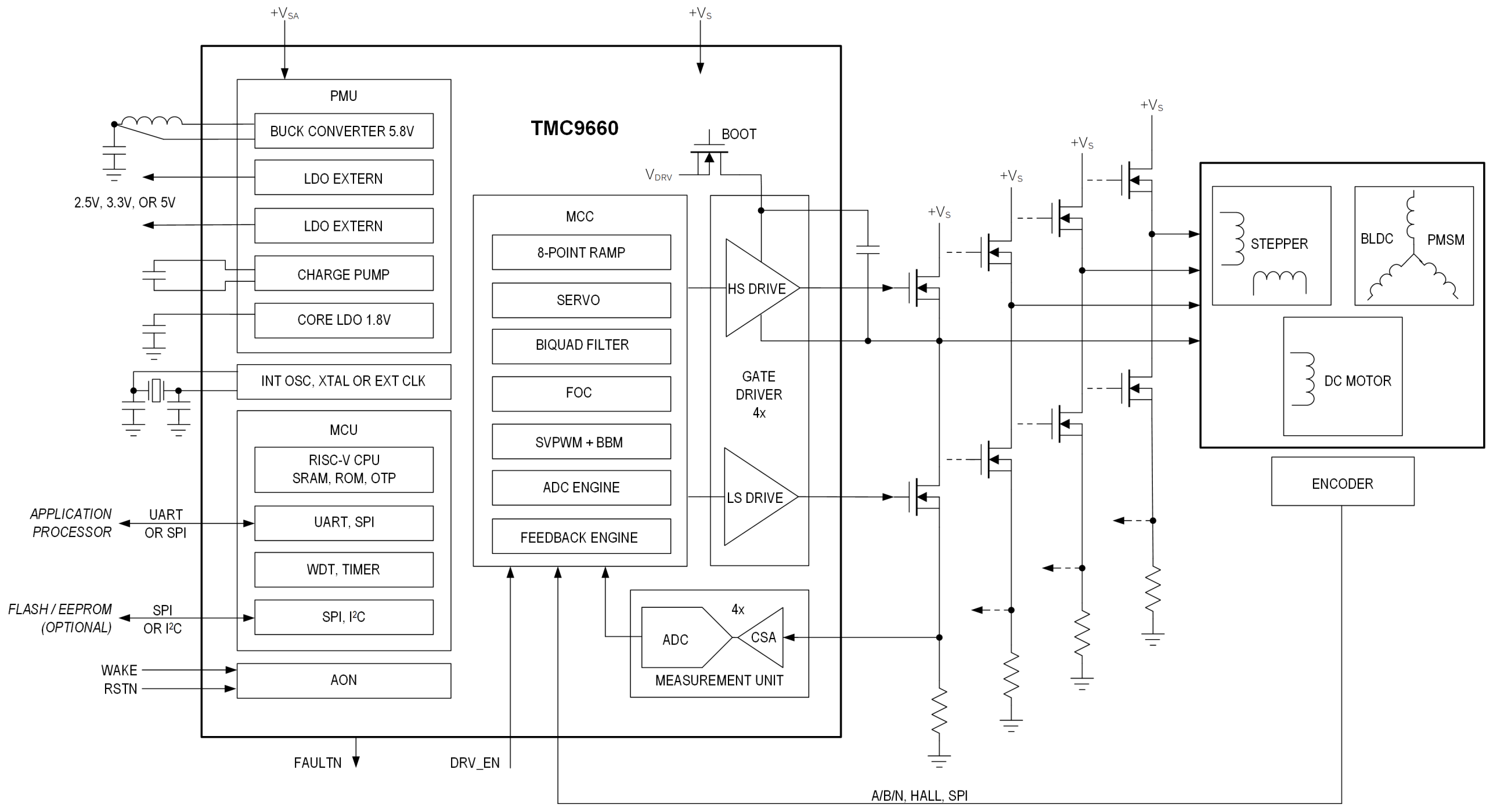
Simplified Block Diagram
TMC9660The “Additional” Engineering Value
First, one solution can meet different requirements. The power requirements of different joints in a humanoid robot vary greatly—fingers need a few watts, elbow joints several hundred watts, and hip joints over a thousand watts. TMC9660 adopts a “gate driver + external MOSFET” architecture. By selecting external MOSFETs of different specifications, one control solution can cover different power requirements ranging from tens of watts to over a thousand watts.
Second, hardware FOC lowers the development barrier. Traditional FOC development requires engineers to write a large amount of code and repeatedly tune parameters. In high-current scenarios, a parameter-tuning mistake can burn the transistors or even the board. TMC9660 hardwires the FOC algorithm in hardware; developers only need to configure parameters to achieve advanced motor control. For low-inductance, hard-to-control motor types such as frameless torque motors, the “deterministic” execution of hardware FOC is more reliable than the “non-deterministic” execution of software FOC (subject to interrupt interference).
V. Conclusion
Frameless torque motors are becoming the “standard” for humanoid robot joints. The motor itself has changed—higher torque density, smaller size, lower weight—and the requirements for drive chips have changed accordingly: low inductance means high current ripple, high di/dt, and high bandwidth requirements. Traditional servo drive solutions (8–20 kHz PWM, software FOC, external op amps) are stretched thin when faced with frameless torque motors. TMC9660 uses a combination of 100 kHz PWM + 100 kHz hardware FOC + integrated CSA to provide a systematic answer.
For more information about TMC9660 or to request samples, please contact: sales@chiplinkstech.com; Mr. Chen, 13924675549.

Sample request attached

WeChat Official Account