
I. 3D Printer Motion System Architecture
Classic desktop FDM 3D printers on the market generally use a standard four-axis motion architecture, corresponding to the X, Y, Z, and E (extruder) axes: the X and Y axes work together to position and move the printhead in the horizontal plane; the Z axis handles vertical layer lifting to switch print height layer by layer; the E axis drives the extrusion mechanism to push filament to the heated nozzle for melting and extrusion. The entire architecture is equipped with four stepper motor driver chips, each independently corresponding to motor control for one axis.
The entire motion system follows a layered signal chain of "logic control—power drive—motor execution," and the drive mechanism can be broken down into three core levels:
The first level is the "main control MCU," which handles motion planning, path calculation, and overall machine logic scheduling, and outputs standard step pulse signals (STEP) and direction signals (DIR) to the driver chip, determining the motor's number of rotation steps and direction.
The second level is the "stepper motor driver chip," the core power conversion unit of the signal chain. After receiving the MCU's digital control signals, it converts them into controlled alternating current in the motor coils, and by precisely adjusting current magnitude and phase, drives the motor to rotate smoothly according to commands. In short, the MCU handles computation and decision-making, while the driver chip handles power output and current regulation.
The third level is the "stepper motor," as the final actuator, which converts the electrical energy output by the driver chip into mechanical rotation, and drives the corresponding axis to move through transmission structures such as timing belts and lead screws.
In the control board hardware layout, driver chips are usually placed side by side immediately next to the main control MCU. Each chip independently corresponds to one motor interface and separately performs current control, overcurrent protection, and operating-state adjustment for a single axis.
II. Load Requirements for Each Axis
1X/Y Axes: Quietness and Dynamic Performance Under High-Speed Reciprocating Motion
The X/Y axes drive the printhead in positioning motion on the plane. During printing, the printhead moves along the X direction for one line, shifts slightly in the Y direction, moves back along the opposite X direction for the next line, and repeats. Motion speed is typically 80–300 mm/s, with frequent acceleration/deceleration transitions. For the driver chip, the key requirement of this axis position is chopping control over a wide speed range.
Stepper driver chips regulate coil current through periodic on/off chopping to maintain target output torque; chopping action produces torque ripple. At low speeds, the chopping frequency falls within the human audible range (20 Hz–20 kHz), generating continuous buzzing noise. The X/Y axes are the most frequently moving axes in the entire machine; in medium- and low-speed printing scenarios, chopping activity is active, and noise performance directly affects user experience.
In high-speed printing and rapid acceleration/deceleration scenarios, the driver chip needs to switch to a high-dynamic chopping mode to ensure stable torque output, avoid step loss caused by insufficient torque at high speed, and support the printhead's rapid response to motion commands. At the same time, continuous high-current operation at high speed also poses a severe challenge to the chip's thermal management.
2Z-Axis: Weight and Power Consumption When Stationary
The Z-axis is responsible for lifting the printhead after each layer is printed; each lift is only 0.1–0.3 mm, at a speed of only 5–10 mm/s. Most of the time, the Z-axis motor is completely stationary, but it must bear the total weight of the X-axis beam, printhead, and cooling fan and must not slide down.
The core requirement this axis places on the driver IC is “standstill current management capability.” When the motor is stationary, it must output sufficient holding torque to prevent the gantry from sliding down under gravity. However, if the standstill current is the same as the current during motion, the coils and core will continuously generate heat. That heat conducts into surrounding structures and may affect heated-bed temperature uniformity and extrusion stability.
Therefore, the driver IC needs to be able to configure standstill current and run current independently and automatically switch between them after the motor stops, thereby controlling heat and power consumption while ensuring holding torque.
3E-axis: Low-Speed Rotation and Microstep Smoothness
The E-axis motor drives a gear train that pushes filament through the hotend nozzle. Its rotational speed is extremely low, possibly only one or two revolutions per second. Tiny fluctuations in E-axis extrusion directly show up on the printed surface, forming periodic vertical fine lines in the Z direction (VFA). At the same time, retraction actions must be performed frequently during printing: during travel moves, the motor quickly reverses to pull the filament back to prevent stringing, and then quickly rotates forward again to resume extrusion.
This axis places two requirements on the driver IC.
First, low-speed microstep smoothness. The higher the microstep resolution, the smaller the current increment per step, and the smoother the low-speed rotation. The accuracy of the chip’s microstep current lookup table directly affects torque uniformity at each step; the finer the table, the lower the current ripple in the low-speed range.
Second, fast direction-reversal response. Retraction requires the driver IC to complete polarity reversal of the coil current within an extremely short time. The speed of current decay and rebuild is determined by the decay mode: too slow decay causes delayed retraction response and stringing; too fast decay increases low-speed current ripple and affects extrusion smoothness. The two must be tuned for balance.
In addition, the E-axis has an inherent limitation of open-loop control: the driver IC sends current commands but cannot confirm whether the motor actually executed them. When a filament clog or extruder jam causes the motor to lose steps, the driver IC cannot detect it. Step loss directly results in insufficient extrusion, causing voids or poor interlayer bonding in the printed part. Whether step loss can be detected is a key differentiator in E-axis selection.
3. TMC2209 vs. TMC2240 Specification Comparison
The TMC2209 and TMC2240 both belong to Trinamic's (now part of ADI) stepper driver chip product line and share the same core technical architecture. The former can be called the most widely used stepper driver chip in the 3D printing field, with the most mature community ecosystem; after years of market validation, it has well-developed firmware support and abundant community resources, and is the standard solution for current desktop printers. The latter, as the manufacturer's new-generation upgraded model, further extends performance and is gradually entering high-end machines and the DIY community. Focusing on these two chips, understanding their differences and trade-offs essentially covers the selection needs from standard entry-level to high-performance advanced models.
| Parameter | TMC2209 | TMC2240 |
| Voltage Range | 4.75~29V DC | 4.5~36V DC |
| Current (RMS) | 2 A RMS (2.8 A peak) | 2.1 A RMS (3 A full scale) |
| On-resistance RDS(on) | 340mΩ(HS+LS) | 230mΩ(HS+LS) |
| Microstep resolution | Pin configuration 8/16/32/64; UART configuration up to 256 | Native 256 |
| Microstep interpolation | MicroPlyer (interpolates low-resolution pulses to 256) | MicroPlyer (consistent) |
| Chopper mode | StealthChop2+SpreadCycle | StealthChop2+SpreadCycle |
| Sensorless detection | StallGuard4 | StallGuard2+StallGuard4 |
| Energy-saving current control | CoolStep (up to 75% energy savings) | CoolStep (consistent) |
| Standstill current management | Automatic Standstill Power Down(IHOLD/IRUN/IHOLDDELAY) | Consistent |
| Passive braking / freewheeling | Supported | Supported |
| Communication Interface | UART (single-wire) | SPI+UART (choose one) |
| Current Sensing Method | External sense resistor (or internal resistor option) | Integrated lossless current sensing (ICS), no external resistor required |
| Encoder Interface | None | ABN incremental encoder interface |
| Closed-loop control | Not supported | Supported (with encoder) |
| Temperature monitoring | None | Chip temperature + motor temperature estimation |
| Package | QFN28 5×5mm/HTSSOP | TQFN32 5×5mm/TSSOP38 9.7×4.4mm |
The two differ in electrical specifications (voltage/current/on-resistance), integration capability, and expansion functions, making them suitable for application requirements with different positioning and providing a clear basis for comparison for per-axis selection. The following analyzes each axis's requirements one by one.
IV. Per-Axis Selection Analysis
1X/Y-Axis Selection
The core requirements for the X/Y axes cover two dimensions: quiet operation at medium and low speeds and dynamic performance at high speeds. Both chips feature StealthChop2 chopper mode and SpreadCycle high-dynamic chopping, and both support automatic switching via a speed threshold; there is no essential difference between the two in terms of chopper control capability.
Therefore, selection should focus on the engineering differences in high-speed, high-current scenarios:
In terms of on-resistance, the TMC2240 has HS+LS 230 mΩ, while the TMC2209 has HS+LS 340 mΩ. At the same current, the TMC2240 has lower conduction loss and generates less heat. The X/Y axes are the most frequently moving of the four axes; during high-speed printing, the driver chip operates continuously at high current, and the difference in on-resistance is directly reflected in chip temperature rise. For standard desktop printers with print speeds within 300 mm/s, the TMC2209's thermal design is sufficient; for high-speed models pursuing speeds above 500 mm/s, the TMC2240's lower on-resistance is better for thermal management.
In terms of current margin, the TMC2240 has a full-scale current of 3 A (OCP limit 5 A), while the TMC2209 has a peak current of 2.8 A. Standard NEMA17 motors mostly have rated currents in the 1.5–2 A range, and the TMC2209 can meet conventional requirements; however, the rated current of some high-torque NEMA17 motors or 0.9° stepper motors (which provide greater torque for the same frame size) may approach or exceed 2 A, and the TMC2240 offers greater current margin.
X/Y-axis selection recommendations: For standard desktop printers (24 V supply, NEMA17 motors, print speeds within 300 mm/s), the TMC2209's specifications are sufficient, making it a mature and cost-effective choice. For high-speed models (pursuing speeds above 500 mm/s and using high-torque motors or 0.9° motors), the TMC2240's advantages in on-resistance and current margin have practical value.
2Z-Axis Selection
The core requirement for the Z-axis is standstill current management, balancing holding torque and low heat generation.
Both chips fully support automatic standstill current reduction, with independently configurable run current, standstill current, and current reduction delay. The current automatically drops after the motor stops, perfectly matching the Z-axis load characteristics. In terms of microstep resolution, both support 256 microsteps (TMC2209 via UART configuration). The Z-axis moves at very low speed, so microstep dynamic error is negligible, and layer-height accuracy is comparable.
The differentiated features of the TMC2240 have limited value in Z-axis scenarios: its on-resistance advantage has almost no effect on heat generation for a long-term stationary axis; encoder closed-loop control cannot solve the problem of mechanical lead screw back-driving after power loss; temperature monitoring offers minimal benefit for a low-load Z-axis.
Z-axis selection recommendation: The TMC2209 is sufficient for Z-axis requirements. The TMC2240's additional capabilities offer no meaningful advantage for the Z-axis.
3E-Axis Selection
The core baseline requirements for the E-axis are low-speed smoothness and reversal response, while stall detection capability is what distinguishes solution tiers.
In terms of low-speed smoothness and reversal response, both chips support 256 microsteps and MicroPlyer interpolation. StealthChop2 mode provides very low torque ripple, ensuring extrusion uniformity; both decay modes and chopper parameters can be flexibly configured via registers. There is no fundamental difference in retraction/reversal performance; it depends more on firmware parameter tuning and the motor's own characteristics.
In terms of stall detection, both chips feature StallGuard sensorless stall detection, enabling basic blockage identification and overload protection. The core difference lies in closed-loop capability: the TMC2240 integrates an ABN incremental encoder interface, can read position feedback, compare the commanded and actual positions in real time, accurately detect motor step loss during blockage or jamming, and automatically correct it; the TMC2209 has no encoder interface and can only rely on StallGuard for basic detection, so it cannot perform accurate closed-loop step-loss correction. However, note that closed-loop operation requires additional encoder hardware and installation space, and not all extruder mechanisms can accommodate it.
In addition, there is a difference in current margin: geared extruders have lower current requirements, and the TMC2209 can meet them; direct-drive extruders have no reduction structure and require higher motor output torque, so the TMC2240's full-scale current margin is more ample.
E-axis selection recommendations: For conventional open-loop applications, the TMC2209 is sufficient. If the extrusion system requires blockage detection and step-loss correction, or uses a direct-drive extruder and needs higher current, the TMC2240 is the more suitable choice.
V. Communication Interfaces and System Design Considerations
Driver chip selection is not only about single-axis performance; engineering factors such as communication interfaces, peripheral component design, and system reliability also affect development difficulty, BOM cost, and long-term overall machine stability, and are practical dimensions to consider during selection.
First, the system adaptability of communication interfaces differs. The TMC2209 supports single-wire UART communication, with up to 4 chips sharing one bus and distinguished by hardware address. It occupies fewer MCU peripheral resources, and wiring and firmware development are simpler, matching the general requirements of a four-axis architecture. The TMC2240 supports selectable SPI and UART dual interfaces. SPI communication has a higher rate and more complete register access, making it suitable for high-performance systems with higher real-time communication requirements, but it requires additional chip-select signals and occupies more IO resources.
Second, the current sensing scheme. The TMC2240 integrates integrated current sensing (ICS), eliminating the need for external precision sense resistors. Each chip can reduce two peripheral components, simplifying PCB routing and lowering BOM cost and material management complexity. The TMC2209 relies on external sense resistors for current sensing. If the internal resistor scheme is enabled, accuracy is lower and temperature drift is large; high-precision applications still require external precision resistors.
Third, temperature monitoring improves the system reliability boundary. The TMC2240 supports chip temperature monitoring and motor temperature estimation; the system can dynamically adjust output current according to temperature: at high temperatures, automatically reduce current to protect the chip and motor and avoid overheating damage; at low temperatures, appropriately increase current to release performance potential. The TMC2209 has no built-in temperature monitoring capability and can only configure the over-temperature protection threshold through fixed parameters, offering lower flexibility.
6. Selection Summary
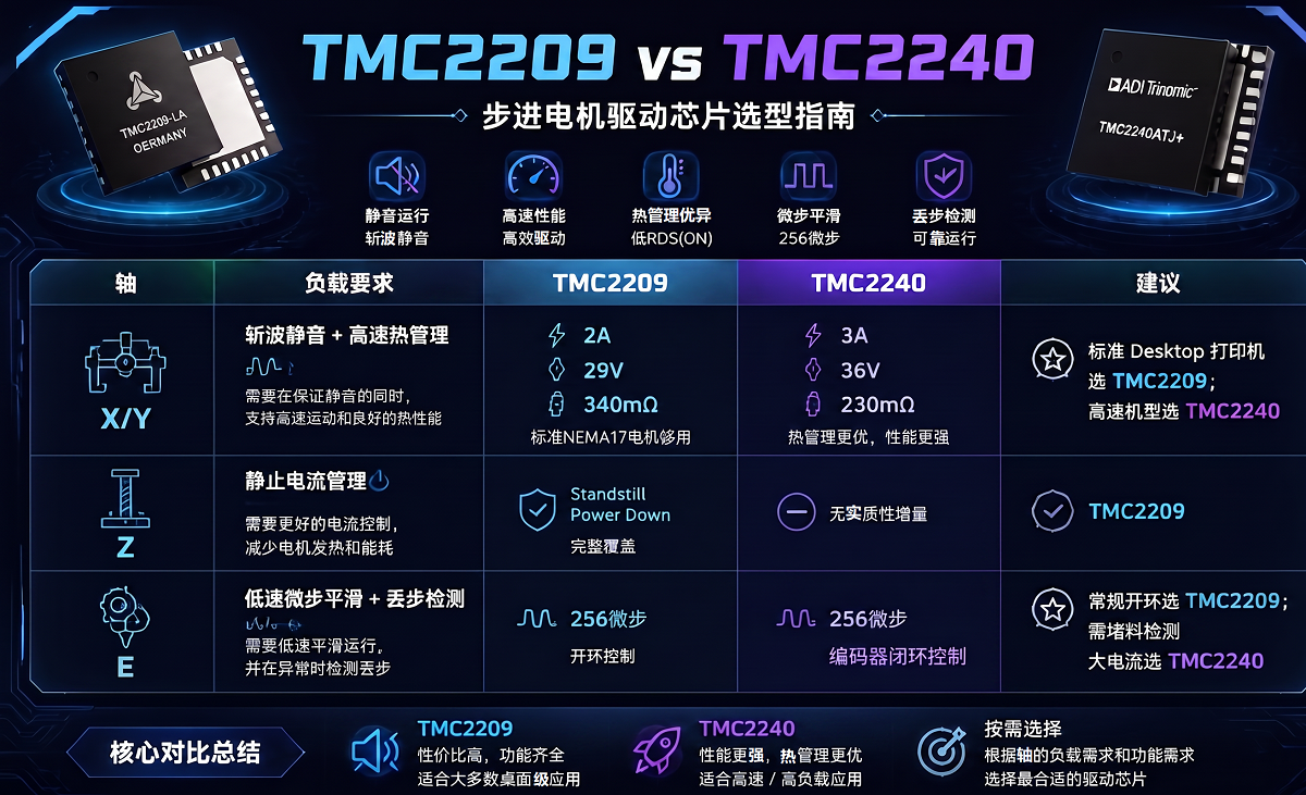
| Axis | Load Requirements | TMC2209 | TMC2240 | Recommendation |
| X/Y | Quiet chopping + high-speed thermal management | 2A/29V/340mΩ; standard NEMA17 is sufficient | 3A/36V/230mΩ; better thermal management | For standard desktop printers, choose TMC2209; for high-speed models, choose TMC2240 |
| Z | Standstill current management | Complete Standstill Power Down coverage | No substantive addition | TMC2209 |
| E | Low-speed microstep smoothing + step-loss detection | 256 microsteps, open-loop | 256 microsteps, encoder closed-loop | For conventional open-loop, choose TMC2209; for jam detection or high current, choose TMC2240 |
Desktop FDM printers are highly sensitive to BOM cost, and the price difference between the TMC2209 and TMC2240 is a practical factor that cannot be ignored in part selection. Viewed individually, both chips can meet the four-axis drive requirements. If only the minimum standard of “basic requirements” is met, per-axis selection loses its meaning.
Entry-level models generally use the TMC2209 uniformly across all four axes. The solution is mature and easy to mass-produce, but there is a performance ceiling under high-speed and high-load conditions. If the entire machine is upgraded to the TMC2240, the Z-axis and standard E-axis cannot leverage the chip's advanced features, making it difficult for the extra cost to translate into actual experience improvements.
Engineering selection follows the principle of "using good steel on the blade"—putting resources where they matter most. A hybrid configuration is a more balanced approach: the X/Y axes use the TMC2240 for better thermal performance and current headroom, while the Z-axis and E-axis use the TMC2209 to control costs. The combination strategy can be adjusted according to product positioning.
This is also where the value of the axis-by-axis analysis in this article lies: invest more in axes that are performance bottlenecks, reasonably control costs on axes where there is no gain, and let the hardware budget go where it can truly improve printing results.
For more information about 3D printer driver selection solutions, please contact: sales@chiplinkstech.com; Mr. Chen, 13924675549.

Sample Request Attached

WeChat Official Account