
In the development of low- and medium-power brushed direct-current motor control systems, motor driver devices often need to provide current monitoring, overload protection, and other functions in addition to basic functions such as power output and PWM speed control. Conventional solutions usually require additional high-power sense resistors and peripheral protection circuits, increasing component count and PCB layout pressure. As an integrated H-bridge motor driver chip, SS6230A integrates H-bridge power transistors, current sensing, current regulation, and fault protection into a single chip, simplifying the motor peripheral circuit design.
1. Product Overview
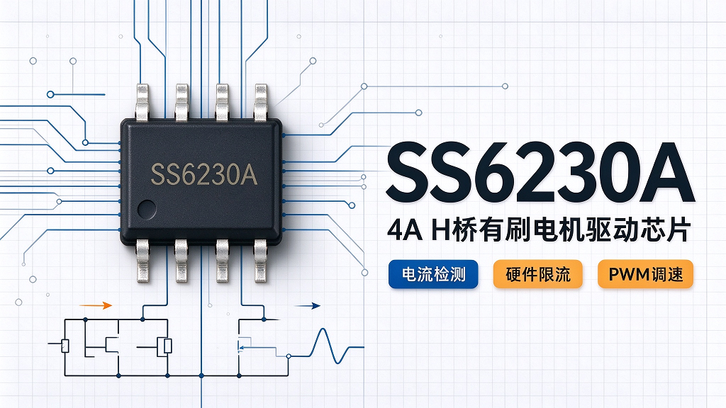
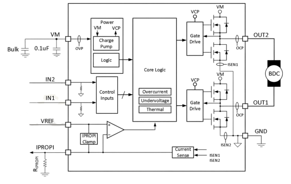
SS6230A is a domestic single-channel H-bridge brushed direct-current motor driver chip in an ESOP-8 package. The chip integrates N-channel H-bridge power transistors, a charge pump, current mirror sensing, current regulation, and multiple fault protections. The chip operating voltage range covers 4.5V~30V, and the peak output current can reach up to 4A. It is designed specifically for low- and medium-power brushed direct-current motor driving.
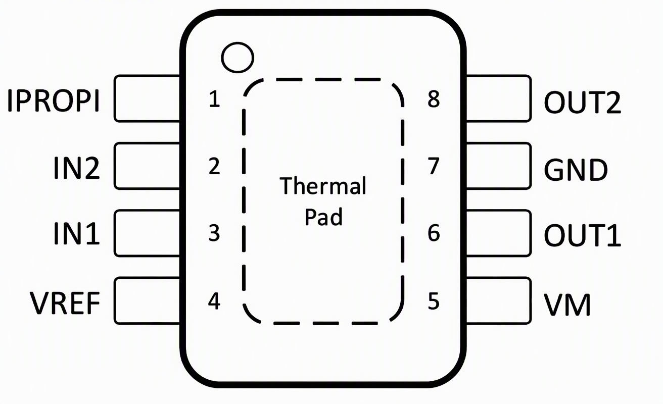
Unlike conventional driver solutions, SS6230A uses an internal current mirror for motor current sensing, eliminating the need for an external high-power sense resistor, reducing peripheral component count, saving cost, and removing the voltage drop and heat caused by additional resistance. The two logic pins IN1 and IN2 control forward rotation, reverse rotation, braking, and high-impedance coasting; the inputs are compatible with 3.3V and 5V logic levels; pulling both pins low at the same time puts the chip into sleep. The chip targets low- and medium-power brushed motor applications such as consumer appliances, smart devices, and some medical devices.
Functional Block Diagram
2. Parameter Analysis
| Parameter Item | Typical / Specification Value |
| Operating Supply Voltage | 4.5V~30V, recommended operating maximum 26V |
| Peak Output Current | VM≥5.5V:4A;
4.5V≤VM<5.5V:3.5A |
| H-Bridge Single-Transistor On-Resistance | 225mΩ, total H-bridge on-resistance 450mΩ |
| PWM Operating Frequency | 0~200kHz, supports 100% duty cycle output |
| Logic input level | Compatible with 3.3V/5V, with a built-in 100kΩ pull-down resistor on the pin |
| Sleep quiescent current | VM=24V, typically less than 1μA |
| Current mirror gain AIPROPI | 1500μA/A, gain error ±5% |
| VREF reference input voltage | 0~3.6V, used for hardware current-limit threshold setting |
| IPROPI output | Current-type output; an external resistor converts it to a voltage for MCU-ADC sampling |
| Protection features | Undervoltage UVLO, overvoltage OVP, overcurrent OCP, thermal shutdown TSD |
| Package | ESOP-8(3.9mm×4.9mm) |
| Operating ambient temperature | -40℃~125℃ |
The chip's maximum operating range of 4.5V~30V can cover common brushed motor systems such as 12V and 24V; output current capability is tied to the supply voltage. When the voltage is below 5.5V, the peak current drops to 3.5A, so current derating under low-voltage conditions must be considered during hardware selection. The H-bridge total on-resistance is 450mΩ; at 1A current, conduction loss is about 0.45W, which is relatively low. The PWM frequency upper limit is 200kHz and supports 100% duty cycle; the speed-regulation range is not limited by high-side drive, adapting to most motor speed-control requirements.
The chip's undervoltage, overvoltage, overcurrent, and overtemperature protection functions are all hardware protection; after most faults are eliminated, the chip can recover automatically. The chip supports current chopping current limiting configured via the VREF pin, independent of overcurrent protection OCP; overcurrent protection (OCP) is mainly used for abnormalities such as short circuits.
Supports a ‑40℃~125℃ operating temperature range; junction temperature upper limit 150℃; thermal shutdown starts at 175℃ junction temperature; meets ordinary consumer devices and some devices with temperature requirements; 24V supply; sleep current less than 1μA; suitable for battery-powered devices to achieve low-power shutdown.
Pinout
Core Features
The chip has a built-in current mirror architecture and outputs an analog current proportional to the motor current through the IPROPI pin. An external ordinary low-value resistor converts it to voltage, and the MCU can read the voltage to complete motor load monitoring, stall detection, and torque judgment. It does not require the high-power shunt resistor connected in series in the power loop in traditional solutions, reducing devices and extra power consumption caused by the shunt resistor and simplifying PCB layout.
The VREF pin together with the external resistor on the IPROPI pin can hardware-set the motor current threshold. When the motor stalls or the load overloads, the chip automatically performs fixed off-time (typical 25μs) current chopping, limiting the output current, protecting the motor and the whole system, without real-time software intervention, improving system reliability.
The H-bridge uses all N-channel MOSFETs, relying on a built-in charge pump to provide boosted drive voltage, so the high-side MOSFETs can remain continuously saturated and on, achieving 100% duty cycle full-speed drive, reducing conduction losses, and improving motor full-speed operating efficiency. Compared with the P-channel high-side scheme, the on-resistance is lower, which helps improve efficiency under high-current conditions. The internal 300ns dead time prevents shoot-through damage to power devices.
The control interface has only two pins, IN1 and IN2: 10 forward, 01 reverse, 11 brake, 00 high-impedance coast. After both pins are pulled low for about 1ms, the chip enters sleep. The input pins have internal 100kΩ pull-down resistors; when the MCU IO is not powered or floating, the H-bridge defaults to high impedance, improving system safety.
4. Practical Case Analysis
Typical Application Circuit
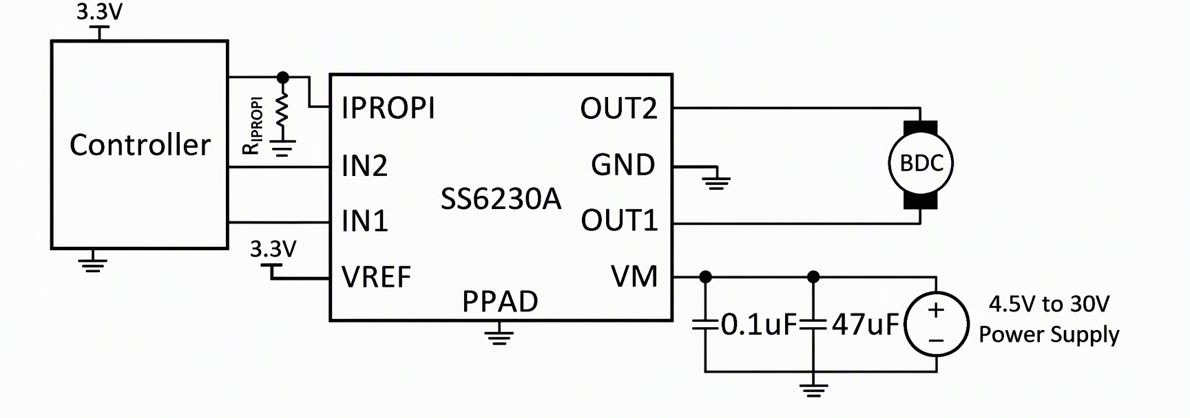
Take a 12V, rated current 0.8A brushed direct-current motor as an example. During normal operation, the current is about 0.8A; during stall, it rises to 2.1A, about 2.6 times the rated value.
When the motor operates normally, the SS6230A drives the motor while scaling down the motor current through a built-in current mirror and outputting it. The relationship between the output current I_IPROPI and the motor current I_MOTOR is:
I_IPROPI = I_MOTOR × A_IPROPI(μA/A)。
whereA_IPROPIisthe current mirror gainwith a typical value of 1500μA/A, i.e., each 1A of motor current corresponds to 1.5mA of output current. Therefore, when the motor current is 0.8A:
I_IPROPI = 0.8A × 1500μA/A = 1200μA = 1.2mA。
The current is converted into a voltage by the external resistor R_IPROPI for sampling by the MCU ADC:
V_IPROPI = I_IPROPI × R_IPROPI (external resistor value).
The design uses a 3.3V system reference voltage, and the MCU ADC range is 0~3.3V. To balance the detection range and the current-limit threshold, the external resistor must be selected in coordination with the current-limit threshold. Under rated conditions, the voltage generated by the 1.2mA detection current flowing through the resistor falls within the ADC range, so the MCU can convert the voltage into real-time motor current, enabling load monitoring and stall detection. Because the power path contains no additional sampling resistor, the 0.8A current does not cause additional voltage drop or power loss in the power path.
The current-limit threshold is set between the rated current and the stall current, at approximately 1.5A. The current-limit threshold is determined jointly by the reference voltage V_VREF and R_IPROPI:
I_TRIP (current-limit threshold) × A_IPROPI = V_VREF / R_IPROPI.
Where the system reference voltage V_VREF = 3.3V and A_IPROPI = 1500μA/A. With 1.5A as the target current-limit value, R_IPROPI is reverse-calculated:
R_IPROPI = V_VREF / (I_TRIP × A_IPROPI) = 3.3V / (1.5A × 1.5mA/A) ≈ 1.47kΩ。
A standard resistance value of 1.5kΩ is selected, and substituting it back gives the actual current-limit threshold:
I_TRIP = 3.3V / (1.5kΩ × 1.5mA/A) = 1.47A。
Under rated conditions, the 1.2mA detection current produces a 1.8V voltage across 1.5kΩ:
V_IPROPI = 1.2mA × 1.5kΩ = 1.8V。
1.8V is within the ADC range of 0~3.3V; based on this, the MCU can derive a motor current of 0.8A.
When the motor stalls, the motor current would naturally rise to 2.1A; however, when the current reaches the 1.47A threshold, the chip's internal comparator triggers fixed off-time current chopping: it turns the output off for a period, then turns it back on after the current drops, repeating this multiple times to limit the current near 1.47A. The entire process is performed by the chip hardware and requires no MCU intervention.
Current limiting also reduces power consumption and temperature rise under stall conditions. The total on-resistance of the H-bridge is 450mΩ, calculated as P=I²R:
At 0.8A, P = 0.8² × 0.45 ≈ 0.29W; at 2.1A without current limiting, P = 2.1² × 0.45 ≈ 1.98W; with current limiting at 1.47A, P = 1.47² × 0.45 ≈ 0.97W.
The chip's thermal resistance is 40.4℃/W; calculations show that the temperature rises under the three conditions are approximately 12℃, 80℃, and 40℃, respectively.Current limiting reduces the stall loss from 1.98W to 0.97W, a reduction of about 51%, and also lowers the stall temperature rise from 80℃ to 40℃, improving the chip's reliability under stall conditions.
Speed control is performed by the PWM signal output by the MCU; the chip directly drives the H-bridge, and the PWM frequency is up to 200kHz. During full-speed operation, the control pin is set to a fixed level, and the H-bridge outputs at 100% duty cycle.
The external components for the entire design include only one 1.5kΩ resistor, one 0.1μF ceramic decoupling capacitor and one electrolytic capacitor at the power supply, two freewheeling Schottky diodes from the two motor output terminals to the power supply and ground, and the thermal copper area and vias corresponding to the ESOP-8 exposed pad. Current sensing, current limiting, and protection are all performed inside the chip, leaving only power supply, freewheeling, and heat dissipation externally.
5. Application Scenarios
SS6230A has 4A peak output, integrated current detection, and hardware current limiting, making it suitable for small- and medium-power brushed direct-current motor equipment where motor stall and sudden load changes may occur:
- Smart consumer appliances: robot vacuum travel/roller-brush motors, coffee machine drive motors, printers, POS receipt printer paper-feed motors;
- Health and fitness equipment: drive mechanisms for various fitness machines, electronic hospital beds, and bed controllers;
- Medical equipment: internal actuator motors for ventilators and surgical supporting equipment;
- Industrial and financial equipment: ATM actuator mechanisms, internal drive motors in electricity meters.
The combination of SS6230A hardware current limiting + current feedback can accomplish overload protection and stall detection, reducing the software development burden for the complete system.
6. Summary
The SS6230A is an H-bridge brushed motor driver chip in an ESOP 8-pin package. Its core advantages are integrated current mirror sensing and hardware current chopping, eliminating the need for an external high-power sense resistor, which helps reduce component count and save PCB space. It supports a maximum supply range of 4.5V~30V and 4A peak output, with multiple hardware fault protections to ensure reliable device operation.
The chip has simple control logic and flexible PWM speed regulation, and supports both software current sampling and hardware overload current limiting, making it suitable for consumer, health, some medical, and industrial control small- and medium-power brushed motor applications.
For more information about the SS6230A or to request samples, contact:sales@chiplinkstech.com; Engineer Chen, 13924675549.
Sample request attached:

WeChat Official Account