
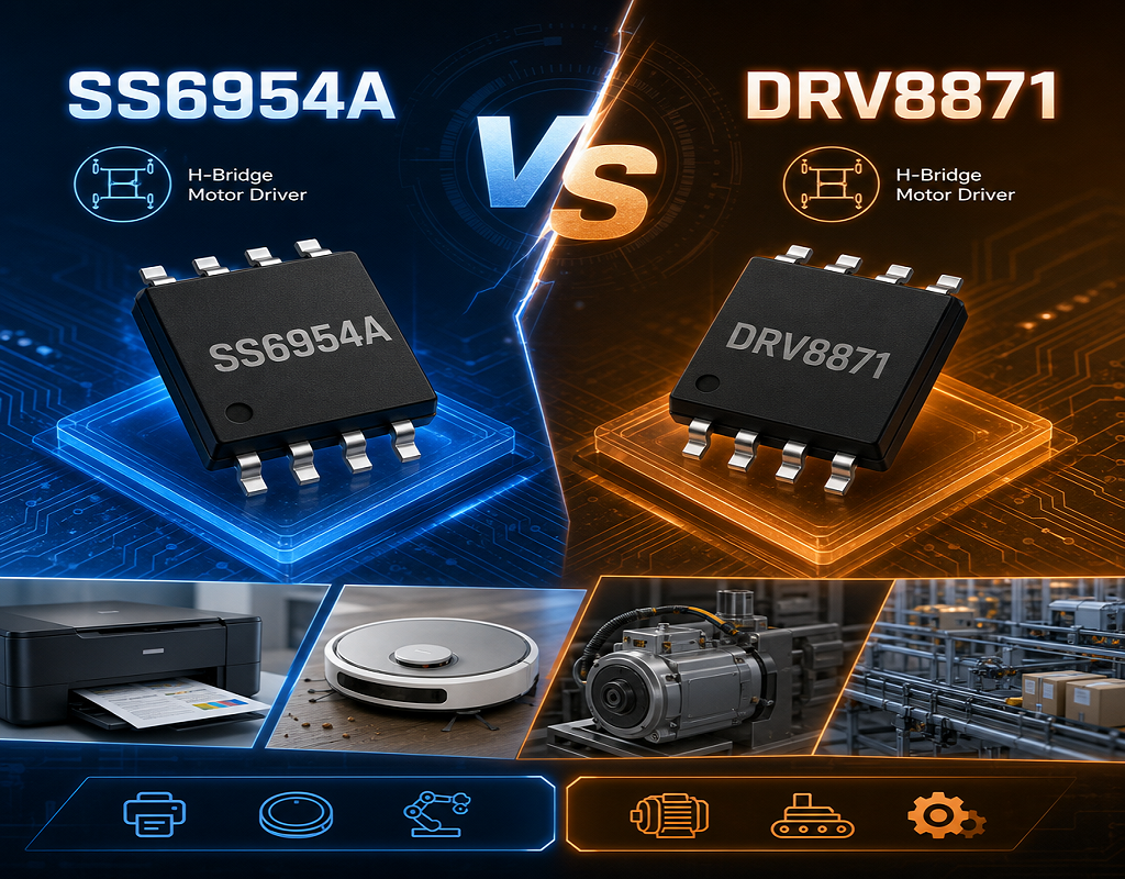
Engineers working on small- and medium-power brushed DC motor drives may be familiar with TI's single-channel H-bridge chip DRV8871; the other option, SS6954A, is relatively niche. Both use a single H-bridge topology with PWM speed control and target home appliance and industrial applications. Their core differences lie mainly in current rating, conduction loss, current regulation method, and thermal conditions.
1. Core Parameter Comparison
In terms of the most critical electrical specifications, the positioning of the two chips differs noticeably.
| Parameter | SS6954A | DRV8871 |
| Operating Voltage | 5.5V~40V | 6.5V~45V |
| Peak Current | 7A | 3.6A |
| Continuous Current | 2.7A | 1A |
| On-Resistance | 200mΩ | 565mΩ |
| Protection | UVLO, OCP, TSD, fault auto-recovery | UVLO, OCP, TSD, fault auto-recovery |
| Package | ESOP8 | HSOP8 |
In terms of voltage coverage, the DRV8871 has an operating voltage range of 6.5 V to 45 V, with a slightly higher upper limit; the SS6954A is 5.5 V to 40 V, with a wider lower limit. For mainstream 12 V and 24 V systems, both can handle back-EMF spikes generated by motor commutation and stall conditions. The SS6954A can also be used in 36 V systems, but it does not leave as much margin as the DRV8871.
Current capability is the biggest differentiator between the two. The SS6954A has a peak output current of up to 7 A and a continuous output of 2.7 A; the DRV8871 has a peak current of 3.6 A, while its continuous RMS current is limited by package thermal dissipation and PCB conditions. In typical designs it is around 0.8–1 A, and with good heat dissipation it can reach about 2 A RMS on standard FR-4 at 25°C. In terms of current specifications alone, the SS6954A is almost one tier higher, corresponding to higher-power motor loads.
The difference in on-resistance is equally significant. The SS6954A has a typical on-resistance of 200 mΩ, while the DRV8871 is 565 mΩ; the former is less than half of the latter. This parameter directly determines the chip's heat generation and efficiency. The higher the current, the more pronounced the difference becomes.
II. Heat Generation and Efficiency: The Gap Becomes Immediately Apparent in High-Current Scenarios
In actual operation, the temperature rise difference caused by on-resistance is more intuitive than datasheet specifications.
Under light-load conditions (within 1 A), neither chip generates obvious heat, so the difference in experience is small. However, when the continuous current rises above 2 A, the DRV8871's 565 mΩ on-resistance causes more noticeable losses and heat, making thermal design necessary. By contrast, the SS6954A's 200 mΩ on-resistance produces losses of only about one third of the former. Estimated at a continuous current of 2 A:
- DRV8871:P≈I²×R=2²×0.565≈26W;
- SS6954A:P≈2²×0.200≈80W。
For scenarios such as massage chair kneading motors and robot vacuum main brushes that run for at least half an hour at a time, the benefits of low on-resistance are not limited to greater chip stability. They can also eliminate the need for heat sinks and simplify airflow duct design, enabling better overall end-product cost.
III. Current Control Solutions: Integrated Saves Components vs. External Flexibility
The two chips take different approaches to current regulation, which is also one of the core bases for selection.
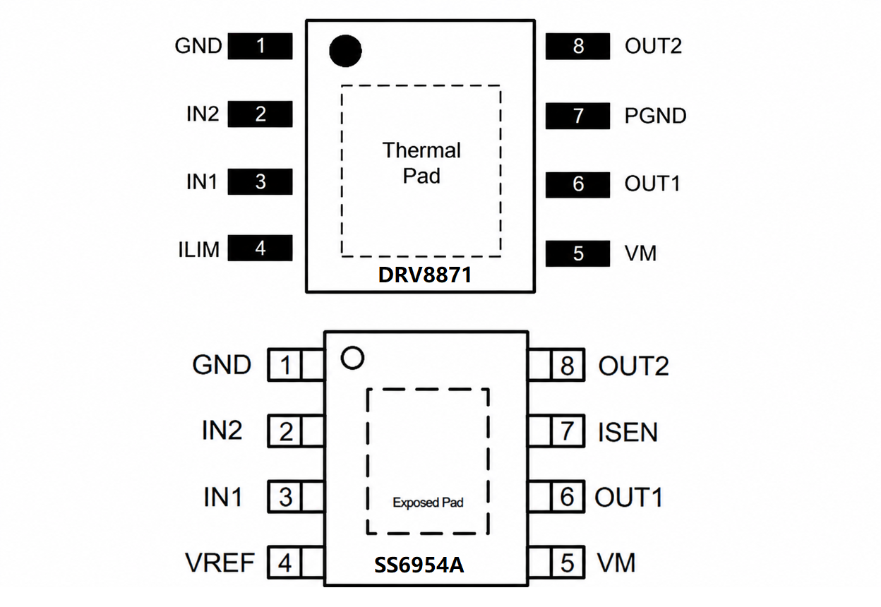
The core advantage of the DRV8871 is its built-in current-sensing architecture. It does not require an external high-power sense resistor; only one ordinary small resistor is needed to set the current threshold, resulting in fewer BOM components and simpler board layout. Its current threshold calculation formula is:
I_TRIP(A)=V_ILIM(kV)/R_ILIM(kΩ)=64(kV)/R_ILIM(kΩ)
For example, RLIM= 32 kΩ, the current-limit point is approximately 2 A; RLIM= 50 kΩ, the current-limit point is approximately 1.28 A. If current adjustment is not required, 15–18 kΩ can be used to let the device deliver a peak of up to about 3.6 A within a few hundred milliseconds. At higher currents, the device will hit overcurrent protection or, due to sustained high current, drive the junction temperature to thermal shutdown; this is not suitable as a normal operating range.
The SS6954A uses an external sense resistor for current regulation, setting the current limit jointly through the VREF analog input and the voltage at the ISEN pin. Its advantages are higher accuracy, more flexible threshold adjustment, and, under high-current conditions, the sense resistor can dissipate heat independently, so losses are not concentrated inside the chip; it is suitable for long-duration full-load scenarios. Note, however, that the SS6954A’s VREF/ISEN sets the current-regulation threshold during normal operation, while its OCP overcurrent protection has an independent threshold. During debugging, do not set the VREF current-limit point too close to the OCP threshold, to avoid directly entering protection and restart during startup or stall.
IV. Package and Protection: Basic Configuration Parity
In terms of packaging, both devices are 8-pin packages. The DRV8871 uses an HSOP8 with a thermal pad, measuring 4.9 × 6 mm; the SS6954A uses an ESOP8 package. Board layout compatibility is comparable, soldering and rework are mature, and the barrier to mass production is low.
For protection, both devices include the full standard set of undervoltage lockout, overcurrent protection, thermal shutdown, and fault auto-recovery, ensuring reliability under normal operating conditions.
V. Selection Conclusion: Match to the Appropriate Current Range
Prefer DRV8871:
For 12V/24V low-power applications with peak current within 3A and a focus on minimal external components and reduced BOM count, such as printer paper-feed mechanisms, small solenoid valves, and lightly loaded appliance motors. The DRV8871 uses internal current sensing, requiring no external sense resistor, which simplifies PCB layout. If a domestic alternative is needed, the SS8870T is also an option: ESOP8 package, 3.6A peak current, and 520mΩ on-resistance (typical), suitable for low-voltage low-power applications with peak current within 3.6A.
Prefer SS6954A:
For higher-power applications in 12V/24V systems with peak current above 3A and within 7A, continuous full-load operation over long periods, and high requirements for temperature rise control, such as massage-chair kneading motors, robot-vacuum main brushes, and industrial conveyor line drives.
Additional TI options:
For the 24V, peak current within 6A applications covered by the SS6954A, consider TI's DRV8874: 6A peak current, 200mΩ on-resistance (typical), integrated current sensing, and no need for a high-power sense resistor. However, its package is HTSSOP16, which is slightly larger. At this current level, TI mostly uses larger packages such as HTSSOP16, and 8-pin high-current single H-bridge options are rare.
Overall, the DRV8871 excels in high integration and simplified external circuitry, making it a reliable general-purpose choice for low-power applications; the SS6954A excels in high current and low conduction loss, and offers better cost-effectiveness in higher-power operating scenarios such as printer paper feed, robot-vacuum side brushes, and massage-chair kneading motors.
For more motor solutions, please contact: sales@chiplinkstech.com; Engineer Chen, 13924675549.

Sample request attached

WeChat Official Account