
The electromechanical assembly of an active linear tonearm—the small stepper motor—generates vibrations directly in the tonearm's mounting fixture, which are then transmitted to the headshell and stylus. These vibrations increase noise, make the headshell vibrate, and degrade the quality of the audio signal. So where do these additional vibrations and noise come from when using a stepper motor?
Noise Sources in Trinamic Stepper Motors
A linear-tracking tonearm is both a very specialized and a typical application for stepper motors, because mechanical equipment needs to be positioned, and positioned very precisely. In general, stepper motors are widely used in almost all types of motion applications, such as automation, digital manufacturing, medical, and optical equipment.
The advantages of stepper motors are relatively low cost, high torque at standstill and low speed without a gearbox, and inherent suitability for positioning tasks. Compared with three-phase brushless motors and servo drives, stepper motors do not necessarily require complex control algorithms or position feedback for commutation.
The disadvantages of steppers arethey are very noisyEven at low speeds or when stationary. Stepper motors have two main sources of vibration: step resolution and side effects caused by chopper and pulse-width modulation (PWM) modes.
Analyzing Trinamic Stepper Motor Resolution and Microstepping
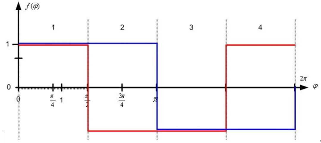
A typical stepper motor has 50 poles, enabling 200 full steps with a step angle of 1.8°, allowing a complete 360° mechanical rotation. However, there are also stepper motors with fewer steps, and even up to 800 full steps. Initially, these motors were used in full-step or half-step modes. The current vector applied to the two motor coils A (blue) and B (red) appears as a rectangle over a complete electrical rotation (360° electrical). As highlighted in the two figures below, the motor coils are energized with full current or no current in a 90° phase-shift pattern. Therefore, one electrical revolution per cycle consists of 4 full steps or 8 half steps. That is, a 50-pole stepper motor requires 50 electrical revolutions to complete one full mechanical revolution.

[Full-step operation (motor coils A = blue and B = red)]

Half-step operation (motor coils A = blue and B = red)
Low-resolution step modes such as full-step or half-step are the main sources of noise in stepper motors. They introduce significant vibration that propagates throughout the entire mechanical system, especially at low speeds and near certain resonant frequencies. At higher speeds, these effects are reduced due to the moment of inertia.
The rotor can be thought of as a harmonic oscillator or spring pendulum, as shown in the figure below. After the driver electronics apply a new current vector, the rotor steps toward the next full-step or half-step position in the direction of the newly commanded position. Similar to an impulse response, the rotor overshoots and oscillates around the next position, causing mechanical vibration and noise. The motion is far from smooth, especially at lower speeds.

The rotor's oscillatory behavior causes vibration
To reduce these oscillations, a mechanism called microstepping can be applied. This divides a full step into smaller parts, or microsteps. Typical resolutions are 2 (half step), 4 (quarter step), 8, 32, or even more microsteps. Instead of energizing the stator coils with full current or zero current, intermediate current levels approximate a complete sine wave over 4 full steps. This positions the permanent-magnet rotor at an intermediate position between two subsequent full steps. This even allows adaptation to the physical characteristics of the stepper motor or application-specific custom current waveforms (TRINAMIC driver chips support this function).
The maximum microstepping resolution is defined by the driver's A/D and D/A functions. Trinamic's stepper motor controllers and drivers allow the use of up to 256 (8-bit) microsteps per full step forstepper motors, using the chip's integrated configurable sine wave table or even fully custom current waveforms.
The result of using this high microstep resolution is that the motor rotor now steps in smaller angles or shorter distances. When switching to a new position, the overshoot and undershoot shown in the figure above are greatly reduced. The figure below shows this difference.

Reduced motor vibration when switching from full-step resolution to high microstep resolution
Chopper and PWM Modes
Another source of noise and vibration comes from the conventional chopper and PWM modes typically used in stepper motors. Due to the dominant effect of coarse step resolution, the parasitic effects of these modes are often ignored. However, as microstepping is used to increase step resolution, these parasitic effects become noticeable and even audible.
The classic constant off-time PWM chopper mode is a current-controlled PWM chopper that operates with a fixed relationship between fast-decay and slow-decay phases. At its peak, the current reaches the specified target current, which causes the average current to be lower than the desired target current, as shown in the figure below.

Constant off-time (TOFF) PWM chopper mode: average current does not reach the target current
During a full electrical revolution, when the sign (direction) of the current changes, this causes a plateau around the zero-crossing region of the sine wave. The effect of this plateau is a brief period in which the current in the motor winding is zero, meaning there is no torque at all. This leads to oscillation and vibration, especially at lower speeds.

SpreadCycle hysteresis chopper with smooth zero crossing
Compared with a constant off-time chopper, Trinamic's SpreadCycle™ (high-precision chopping algorithm) PWM chopper mode uses hysteresis and automatically applies a matched relationship between slow-decay and fast-decay cycles. The average current reflects the configured nominal current. There is no plateau in the zero-crossing region of the sine wave. This reduces current and torque ripple and approaches a true sine waveform, making the motor run more smoothly than with a constant off-time PWM chopper. This is especially important at standstill and at low to medium speeds.
The TMC5130A-TA is a small intelligent stepper motor driver and controller IC with StealthChop mode, the ultimate solution for this outstanding analog turntable. In addition to StealthChop, Trinamic has improved voltage-mode operation and combined it with current control. To minimize current fluctuations, the driver in the TMC5130A-TA chip adjusts voltage modulation based on current feedback. This allows the system to self-adjust according to motor parameters and operating voltage.
How do you make a stepper motor completely silent?
Although microstepping reduces most of the vibration caused by low step resolution, high microstep resolution can make other vibration sources more perceptible. Advanced current-controlled PWM chopper modes, such as Trinamic's SpreadCycle™ (high-precision chopping algorithm) algorithm, implemented in hardware, greatly reduce vibration and jitter. This is sufficient for many standard applications and is also very well suited to high-speed applications.
But even with current-controlled chopper modes such as SpreadCycle, a small amount of audible noise and vibration can still occur due to unsynchronized motor coils, millivolt-level regulation noise on the sense resistor, and PWM jitter. This noise and vibration are critical for high-end applications, low-to-medium-speed applications, and any application where noise is unacceptable. For the Dereneville DTT-01-S linear tracking tonearm, this is intolerable, because noise from the microstep driver and hybrid stepper motor would be superimposed on the audio signal, especially in the ordinary grooves between individual tracks.
Trinamic's StealthChop™ algorithm [4] is also implemented in hardware and ultimately makes the stepper motor silent. But how does StealthChop actually silence the motor, and why does it not generate additional noise and vibration? Compared with current-based chopper modes such as SpreadCycle, StealthChop uses a different approach: it is a voltage-chopper-based technology responsible for the noise-free and smooth movement of the Dereneville DTT-01-S tonearm and stylus. Combined with closed-loop tracking angle adjustment and precision laser optics, this makes the maximum tracking angle error of the headshell and stylus<0.05°. A good conventional pivoted tonearm has<a typical tracking angle error of 2°–3°, and is also affected by skating force and mechanical wear of the grooves.
The TMC5130A-TA is a small intelligent stepper motor driver and controller IC that includes StealthChop mode, and is the ultimate solution for this exceptional analog turntable. In addition to StealthChop,Trinamic it also improves voltage-mode operation and combines it with current control. To minimize current ripple, the driver of the TMC5130A-TA chip adjusts voltage modulation based on current feedback. This allows the system to self-adjust according to motor parameters and operating voltage.
eliminates the small oscillations caused by the regulation algorithm of the DC control loop. Because SpreadCycle and other current-regulation chopper principles always react cycle by cycle to coil current measurements, there is always noise of a few millivolts in complex systems, as well as electromagnetic coupling between the two internal coils. This leads to tiny variations in the resulting motor current, which in turn affect the chopper.
The following two figures compare voltage-controlled StealthChop and current-controlled SpreadCycle. StealthChop's zero-crossing behavior is perfect: when the sign of the current value changes from positive to negative or vice versa, there is no plateau; instead, the zero current level is crossed in a straight line, because the current is based on the modulated PWM duty cycle. At 50% PWM duty cycle, the current is effectively zero.

Sine wave of one motor phase in voltage-controlled StealthChop™ chopper mode

Sine wave of one motor phase in current-controlled SpreadCycle™ (high-precision chopper algorithm) chopper mode

Magnified PWM view of the motor phase and coil current in voltage-controlled StealthChop™ chopper mode

Magnified PWM view of the motor phase and coil current in current-controlled SpreadCycle™ (high-precision chopper algorithm) chopper mode
Motor drivers equipped with StealthChop combine a current waveform that is very similar to analog—which is in some ways ideally suited to Dereneville analog cassette deck applications—with some minor improvements in power consumption at no additional cost. The result is whisper-quiet motion. Apart from unavoidable ball bearing noise, StealthChop provides exceptionally quiet stepper motor performance. Applications using StealthChop have achieved noise levels 10 dB lower than classic current control. As we know from physics, a -3 dB change represents roughly half the noise or sound level reduction.
The figure below shows the final controller PCB for the tonearm's electromechanical actuator and Trinamic's intelligent stepper motor driver solution. It was designed and manufactured by Dischereit.

Controller PCB for the electromechanical actuator of the DTT-01-S tangential tonearm, along with Trinamic's intelligent stepper motor driver solution. (Courtesy of AVDesignHaus)
Summary and Conclusion
The new fully automatic tangential tonearm Dereneville DTT-01-S for the outstanding Dereneville Modulaire MK III analog turntable redefines the standards of the analog HiFi world. It is truly the first of its kind. For ultra-quiet operation, the tonearm relies on the TMC5130A-TA stepper motor driver and controller. This smart IC features StealthChop mode, enabling ultra-quiet stepper motor operation (no noise and physical vibration) and adding the necessary final touch to this perfect engineering: it is responsible for delivering the pure sound that audiophiles love to hear, as loud as possible.
Although, given the IC business, the manufacturing volume of this exclusive analog chip may be relatively low, there are many similar applications that can take advantage of this smart IC technology. These include wafer handling in semiconductor manufacturing equipment, medical applications, and laboratory automation. They all have similar performance requirements for low noise and low vibration. In addition, there are other applications so far that have lower requirements for noise, vibration, and motion quality, and these applications can be significantly improved by this technology. There is also a growing number of emerging embedded applications that are actually only possible through this smart solution—from both qualitative and quantitative perspectives. These include, for example, 3D printing and desktop manufacturing applications, advanced personal medical devices where audible noise is unacceptable, camera sliders, and advanced CCTV and surveillance cameras. The TMC5130A series ultimate stepper motor drivers and controllers reflect the major trend in motion control.