
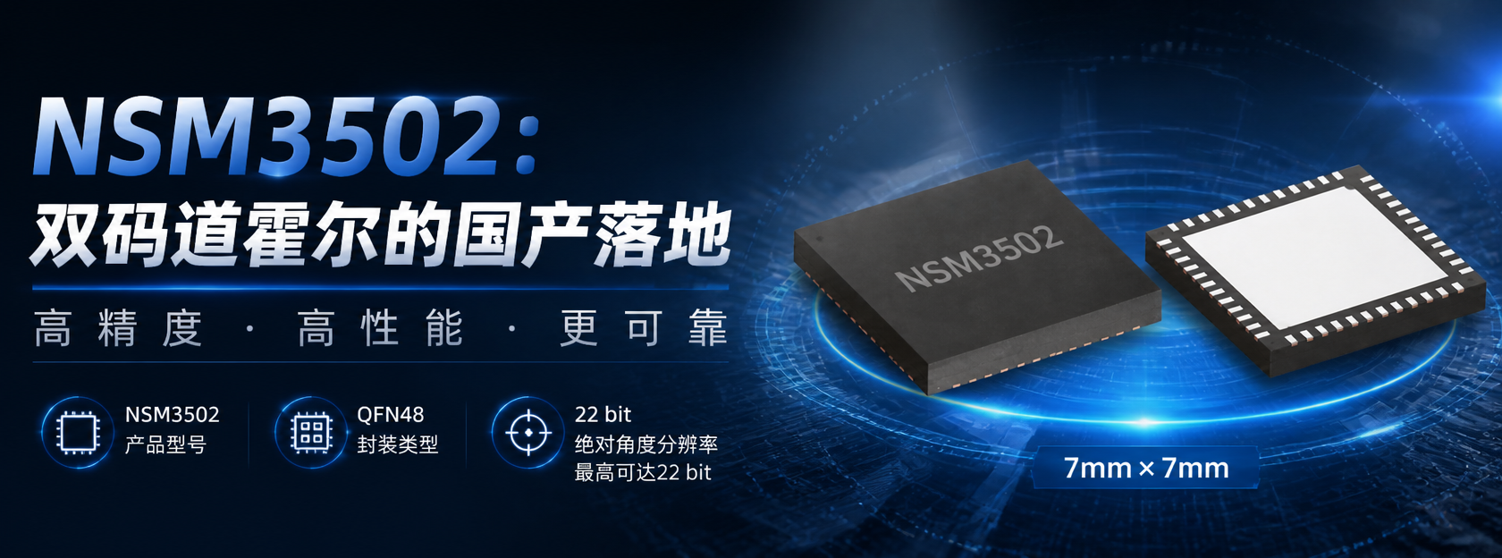
At the end of July 2026, NOVOSENSE released the NSM350x series, the first domestic dual-track Hall encoder family. It includes the NSM3500, NSM3501, and NSM3502, corresponding to vernier magnetic rings with 1.28 mm, 1.5 mm, and 2 mm magnetic pitch, respectively. The entire series is compatible with 16-, 32-, and 64-pole-pair outer-track designs, meeting diverse application needs. Currently, the NSM3502 is the first to be available for sample requests.
On the international market, semiconductor companies such as iC-Haus of Germany and Broadcom of the United States have been working on the “dual-track vernier algorithm” technology route for many years. In the field of domestic chips, however, the NSM350x is the first to integrate Hall-effect sensing with a dual-track vernier architecture on a single chip.

1. Why Dual-Track Hall Encoders Are Needed
1Hollow Joint Design: Off-Axis Becomes Essential
Joint modules for collaborative robots and humanoid robots are evolving toward hollow designs. Power lines, encoder signal lines, brake control lines, and even cooling pipes need to pass through the center of joint rotation. The traditional shaft-end encoder approach—in which the sensor is mounted on the rotating shaft—directly occupies axial space, forcing cables to route around it and increasing wiring complexity and joint volume.
The off-axis approach emerged to address this: the sensor is moved to the side of the rotating shaft, the magnetic ring rotates around the axis, and the chip senses magnetic field changes from a radial position. The sensor no longer “blocks” the axis center, enabling a hollow structure.
2Four technology routes, each with its own trade-offs
Off-axis mounting itself is not difficult to implement. There are currently four mainstream technology routes: optical, inductive, capacitive, and magnetic. All support off-axis architectures. The main differences lie in how high the accuracy is and how heavy the cost burden is after going off-axis.
In terms of accuracy, optical solutions are the benchmark; encoder discs can achieve arcsecond-level precision. However, optical code discs have almost no tolerance for dust and oil contamination. Aluminum chips and lubricating oil in collaborative robot workshops are a fatal environment for them—even with sealing, long-term reliability remains a problem. The hollow-shaft optical solution is even more so: cost confines it to high-end machine tools.
The inductive route has the most outstanding overall performance in off-axis scenarios. It does not rely on a permanent magnetic field, so motor magnetic leakage cannot affect it; dust and oil contamination also do not affect eddy current sensing. Take NOVOSENSE's own MT6901 as an example: with a dual-track vernier algorithm, it can achieve up to 23-bit output and is suitable for harsh industrial environments. The cost of the inductive route lies mainly in materials—a precision-machined metal target disc is needed to replace the magnetic ring, and if the target disc's flatness is even slightly poor, the accuracy curve collapses. Mass-production cost is relatively higher than that of the magnetic route.
Capacitive solutions can be made very small with extremely low power consumption, but in mainstream collaborative robot joint applications, their accuracy and resolution do not have an advantage over magnetic and inductive solutions.
Among these four routes, the magnetic route has the most balanced cost-performance in joint scenarios. A magnetic ring is simply a magnetized ferrite or NdFeB piece, far cheaper than optical code discs and metal target discs; its tolerance to dust and oil is also far higher than that of optical; and its accuracy is sufficient in most industrial scenarios. At the same time, as production volume increases, material costs naturally fall. Therefore, in scenarios that are cost-sensitive, space-constrained, and have controllable motor magnetic interference, Hall solutions remain a pragmatic choice. Within magnetic solutions, there are different technology branches such as Hall, AMR, GMR, and TMR. The NSM350x series uses Hall technology, which is the most mature, lowest-cost, and most widely used. Among domestic products, traditional off-axis solutions are mainly single-track Hall encoders. To understand why these solutions are insufficient, we need to look at two levels: the capability ceiling of the single-track architecture itself, and the engineering challenges shared by all magnetic encoders.
3Limitations of a single track
A single-track Hall encoder uses a Hall array to sense the magnetic field signal of a single track, and within a single pole pair it can output the absolute angle within that pole pair. However, on a multi-pole-pair magnetic ring, it cannot distinguish which pole period it is currently in—at the same mechanical angle position in different pole pairs, the magnetic field distribution sensed by the Hall array is the same. After power-up, a Z signal or mechanical homing is required to determine the mechanical position. The dual-track vernier architecture bypasses this limitation: two tracks with different pole pitches produce different electrical angle readings at the same mechanical angle, the phase difference is unique over a full revolution, and the vernier algorithm directly obtains the full-revolution mechanical angle in one calculation.
For multi-axis collaborative robots, performing full-axis homing every time power is applied is not only time-consuming but also increases mechanical wear.
4Scenario Challenges
Off-axis mounting means the chip is located immediately adjacent to the motor body. The rotor leakage flux of the permanent magnet synchronous motor and the stray magnetic fields generated by winding currents can produce interference on the order of tens of mT at the sensor location. Typically, either a high-permeability magnetic shield is added (increasing volume and BOM cost), or accuracy loss is accepted.
In addition, a sensor's nominal accuracy is measured under ideal mounting conditions. On the production line, the actual situation is: PCB placement has positional deviation, magnetic ring assembly has eccentricity, and mechanical structures have cumulative tolerances. If the sensor requires mounting accuracy on the order of 0.05 mm, the production line needs precision positioning fixtures and unit-by-unit calibration, which is another huge cost for consumer-grade or high-volume industrial products.
II. Dual Track + Hall: NSM350x Technical Solution (Taking NSM3502 as an Example)
1Core Architecture: Coordination of the Master Track and Nonius Track
The sensing core of the NSM3502 is two Hall arrays integrated on-chip, corresponding to the Master Track and the Nonius Track, respectively.
The two Hall arrays each sense the sine/cosine magnetic field variations generated by rotation of the magnetic ring. After amplification and filtering by the analog front end, the signals are converted to digital quantities by the ADC and enter the DSP for arctangent angle calculation. There is a slight difference in pole pitch/number of pole pairs between the two code tracks. Through a vernier algorithm, a phase difference operation is performed on the two angle signals, ultimately synthesizing a single-turn absolute mechanical angle. This principle is similar to the 'main scale + vernier scale' combination of a vernier caliper, achieving higher absolute position resolution through phase difference.
This workflow can be summarized as: Hall array → analog front end (amplification, filtering) → ADC → DSP (compensation, calibration, vernier synthesis) → output interface (SPI / UART / ABZ / UVW / PWM).
After synthesis, the NSM3502 achieves an absolute angle resolution of up to 22 bits, corresponding to a typical DNL (differential nonlinearity) of ±0.005°.
2Differential Hall: inherent interference immunity
The NSM3502 uses a differential method to detect the magnetic field component perpendicular to the chip surface. The differential structure inherently provides common-mode rejection: external stray magnetic fields (such as motor leakage flux) affect the two differential Hall elements almost identically and are canceled in the differential output.
This means that in strong-interference environments such as next to a motor, the chip can maintain its nominal accuracy without relying on an external magnetic shield. For space-constrained robotic joints, eliminating the shield's volume and cost directly translates into design margin.
3Four-tier accuracy compensation mechanism: select as needed
The gap between a magnetic encoder's nominal accuracy and its accuracy in an actual system mainly comes from non-uniform magnetization of the magnetic ring, installation eccentricity, mechanical tolerances, and temperature drift. The NSM3502 provides a four-tier progressive accuracy compensation mechanism:
- Factory baseline calibration.Done at the chip factory; it handles offset, gain mismatch, and temperature compensation of the Hall array itself. The calibrated typical INL (integral nonlinearity) is ±0.5°, providing basic plug-and-play accuracy.
- Simple client-side self-calibration.After the engineer installs the chip and magnetic ring in place, rotate the magnetic ring at a non-uniform speed—no precision turntable is required; the speed should be between 40 and 3000 pole pairs per minute and cover at least 16 pole pairs—then pull the CAL_EN pin high or write to the register to trigger calibration. The chip's internal algorithm automatically compensates for offset, amplitude error, and phase error caused by uneven magnetization of each pole pair. After calibration, INL drops to ±0.3°.
- Vernier fine adjustment.Performed using NOVOSENSE's companion programmer and PC software; it calibrates the vernier error introduced by the magnetic ring and installation and involves precision parameters inside the vernier algorithm. It must be performed after the simple self-calibration.
- Constant-speed self-calibration.Provided that vernier fine adjustment has been completed, the system runs at a constant speed (speed fluctuation < ±3‰) and rotates for more than 64 revolutions. The chip automatically calculates nonlinearity compensation parameters and burns them into EEPROM. After completion, the typical INL drops to ±0.1°.
Calibration status can be monitored in real time via the PWM pin waveform or the SPI CAL_STATE register. Calibration parameters are automatically saved to the built-in EEPROM and automatically loaded on subsequent power-up, so recalibration is not required at every startup. Each level of accuracy compensation has its own usage conditions and expected results; engineers can choose according to actual requirements.
III. Applications: Engineering Adaptability
The 22-bit resolution and four-layer calibration system address the question of "how to measure accurately." Below, we examine the engineering adaptability of the NSM3502 from three perspectives: mechanical installation, diagnostic alarms, and output interfaces.
1Mechanical Design Freedom of Off-Axis Installation
The mechanical installation parameters of the NSM3502 directly reflect the engineering advantages of the off-axis solution:
| Parameter | Typical Value | Allowed Range |
| Distance from chip surface to magnetic ring surface | 0.6mm | 0.2~1.0mm |
| Permissible chip radial deviation | — | ≤0.5mm |
| Permissible chip tangential deviation | — | ≤0.5mm |
| Encoder disk eccentricity | — | ≤0.1mm |
A radial and tangential tolerance of 0.5 mm means that chip mounting does not require a precision positioning fixture. At the PCB placement accuracy of most robot joint modules, this tolerance band is sufficient.
The magnetic ring supports three pole-pair configurations—16, 32, and 64—corresponding to main code track diameters of 20.37 mm, 40.74 mm, and 81.49 mm, respectively, covering the size range from small collaborative robot joints to large industrial joints. Taking the 32-pole-pair configuration as an example, the distance from the chip center to the axis is 18.37 mm, corresponding to a hollow bore diameter of about 36 mm—enough to route power and signal harnesses through. The maximum speed supported by the chip also differs by pole-pair count: up to 24000 RPM with a 16-pole-pair magnetic ring, 12000 RPM with 32 pole pairs, and 6000 RPM with 64 pole pairs.
2Diagnostics and Alarms
The NSM3502 integrates a multidimensional diagnostic system internally and outputs alerts through the DIAG_CODE register and FAULT pin:
- Weak/strong magnetic field alarm:Corresponds to abnormal magnetic ring mounting distance, or magnetic ring demagnetization or absence;
- Overspeed alarm:Internal resolved speed exceeds the threshold (configurable to 100/200/400/600 Hz);
- NVM CRC check failure:EEPROM data integrity error—no debounce is applied for this item, and an alarm is triggered directly;
- Undervoltage alarm:Triggered when the supply voltage is below 2.55 V; recovery threshold is 2.75 V (25% hysteresis);
- Overtemperature alarm:Triggered when the internal chip temperature exceeds the alarm threshold (user-defined); hysteresis is configurable to 0.5°C or 1°C. The NSM3502 operating temperature range is -40°C to 125°C.
Fault detection includes debounce logic: the fault flag is set only after 16 consecutive fault cycles and cleared only after 64 consecutive normal cycles, preventing false alarms caused by transient interference. The only exception is NVM_CRC—memory-level hard faults do not require debouncing.
After fault confirmation, chip behavior is configurable: the DIAG_ENC_RST register determines whether ABZ/UVW outputs continue or are forced to zero during a fault. For safety-critical systems, the latter prevents the host from consuming an angle value that "looks normal but may be incorrect."
3Output Interfaces
The NSM3502 supports five output modes—ABZ, SPI, UART, PWM, and UVW—each targeting different scenarios:
- SPIProvides complete 22-bit angle data and full register/EEPROM operation capability. Write operations require a double safety lock: first send the service mode key (0x5E5A3E) to enter service mode, then write 0x185E to address 0x86 to enable user write permission. Fast Read mode supports pipelined continuous reading; in the current frame, MISO returns the data requested in the previous frame, improving the effective update rate.
- PWMOutput resolution is 12-bit; frequency is programmable in three settings—1 kHz, 2 kHz, and 0.5 kHz. Polarity is invertible; rise/fall times are within 1 µs.
- ABZResolution is programmable from 1 to 65,536 pulses/revolution, and Z-signal width is configurable. At 65,536 pulses/revolution, the maximum frequency is 4.096 MHz; above this frequency, INL degrades.
- UVWAnalog commutation signals with programmable output of 1 to 64 pole pairs per pole pair; one chip simultaneously handles commutation and position feedback.
- UARTSupports 2.5 Mbps and 4 Mbps, with a Safety function enable bit and a 94-byte user-defined data area.
IV. Positioning: NSM350x Market Coordinates
The positioning of NSM350x needs to be verified in two coordinate systems: first, within NOVOSENSE's own product line, what are the differences between it and existing models; second, in the market, where does it stand relative to international competitors.
1Internal Coordinates: Position Within Its Own Product Line
NOVOSENSE has previously built a magnetic encoder product portfolio covering Hall-effect and AMR magnetoresistive types. In early 2026, it launched the MT6901 dual-track vernier-algorithm inductive encoder chip based on eddy-current sensing. With the release of the NSM350x series, NOVOSENSE has become the first domestic chip company to offer dual-track vernier encoder products based on both magnetic sensing and eddy-current sensing technology routes.
The positioning differences among the models are clearly delineated by technical route:
- MT6901 (eddy-current sensing + dual-track vernier): high accuracy, insensitive to dust, oil contamination, and strong magnetic interference, targeting harsh industrial environments;
- MT6620/MT6728 (Hall + single-track): supports off-axis mounting, single-track architecture, lower accuracy;
- NSM350x series (Hall + dual-track vernier): implements a dual-track vernier architecture on the Hall technology route.
In NOVOSENSE's product matrix, the NSM350x series fills the gap for "Hall + dual-track vernier."
2External positioning: benchmarking against international competitors
The "Hall + dual-track vernier" solution has over a decade of development history in the international market. Several mainstream products outline the competitive landscape of this technology route:
Germany's iC-Haus iC-MU series is a mature representative of this route. iC-MU integrates Hall sensors and provides absolute position within a single mechanical revolution through two independent channels: the main track and the vernier track. It offers three pole pitch specifications: 1.28 mm, 1.5 mm, and 2.0 mm — among them, the iC-MU200's 2.0 mm pole pitch is the same as that of the NSM3502, and the iC-MU200 has passed AEC-Q100 automotive qualification. The absolute angular resolution of iC-MU varies with the number of pole pairs: 18 bits at 16 pole pairs, 19 bits at 32 pole pairs, and 20 bits at 64 pole pairs (after filtering). Interfaces support SSI, BiSS, SPI, and incremental signal output.
Broadcom AEAT-9988M uses an integrated Hall element and dual-track magnet design, with programmable absolute resolution from 16 to 23 bits, programmable incremental ABI resolution from 1 to 65536 CPR, and UVW commutation signals supporting 1 to 64 pole pairs.
The 22-bit resolution of the NSM3502 is within the mainstream range of the above products. On the track of "Hall principle + dual-track vernier algorithm," international manufacturers' products have undergone multiple generations of iteration and extensive application validation; in terms of parameters, the NSM3502 is still slightly inferior to top-tier products. Its value lies in providing the market with a usable domestic solution.
V. Conclusion
The release of the NSM350x series has enabled domestic magnetic encoders to secure a from-zero-to-one foothold on the “Hall + dual-code-track vernier” technical route.
From the perspective of NOVOSENSE’s own evolution, the MT6620 achieved off-axis sensing with a single-code-track Hall element; the MT6901 advanced to a dual-code-track vernier on the eddy-current sensing route; and the NSM350x series brings these two lines together—implementing a dual-code-track vernier architecture based on the Hall principle. The three chips address problems in different scenarios and together form NOVOSENSE’s product matrix in the off-axis encoder market.
From an industry perspective, having a domestic option on a technical route means downstream manufacturers of collaborative robots, humanoid robots, AGV steering wheels, and similar products have one more choice in their supply chain. The practical value of this choice—cost, lead time, localized technical support, and so on—is often more important than the decimal points in a parameter table.
NSM3502Sample applications are now open. For more information or to apply for samples, please contact: sky.xu@chiplinkstech.com; Mr. Xu, 18820174321.
Sample application attachment:

WeChat Official Account
